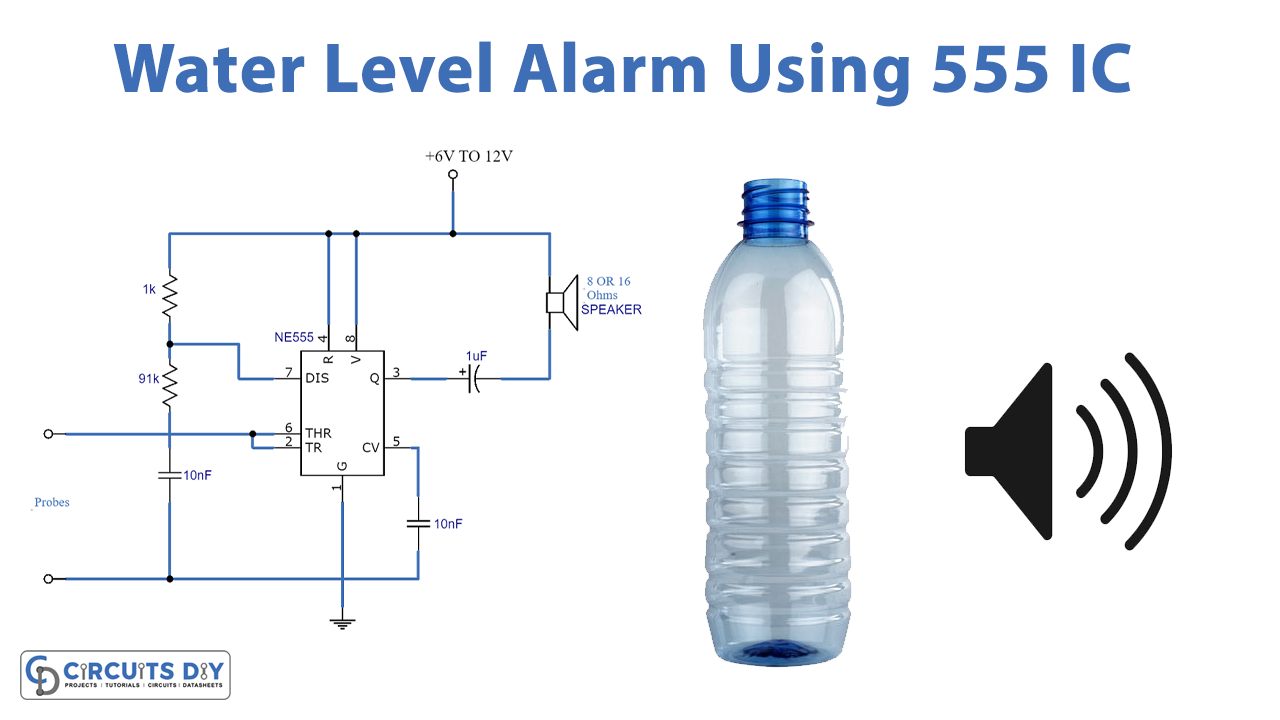
In this circuit, we are making a project of a water alarm circuit using 555 IC. It will produce a sound alarming you when the water reaches the desired level. Water overflow is a major issue and almost all of us face this in our everyday lives. There are lots of solutions to these problems like ball valves etc but if you are someone who likes using electronics to overcome problems then this tutorial is for you.
This circuit is using a 555 timer IC which is the main component. 555 timer IC is working as an astable multivibrator. This circuit is simple and inexpensive because it using only a few components other than this IC such as probes, resistors, capacitors, speakers, and a battery or power supply.
Hardware Components
| S.no | Component | Value | Qty |
|---|---|---|---|
| 1. | Input Supply DC | 6-15V | 1 |
| 2. | Probes | – | 2 |
| 3. | Resistor | 1KΩ, 91KΩ | 1, 1 |
| 4. | Capacitor | 10nF, 1µF | 2, 1 |
| 5. | Speaker | 8 or 16Ω | 1 |
| 6. | IC | NE555 Timer | 1 |
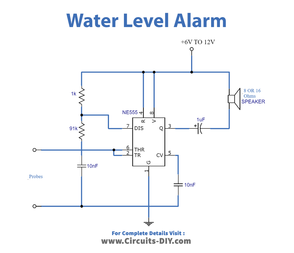
Circuit Diagram
Working Explanation
Place the probes on the desired level of water you want to be notified of. When the water reaches that level it sends a trigger pulse to the input of 555 IC and it gives an output pulse. This output pulse will activate the speaker and you will hear an alarm sound. Smoothing Capacitor is used at the output to filter out the noise before going to the speaker.
This circuit can be operated on voltages ranging from 6 to 15V. use the speaker of 8 or 16 ohms with 0.5 to 1-watt output ratings.
Applications and uses
- Water tanks
- Swimming pools
- Aquariums
- Containers, etc.