Introduction
The water level indicator is very effective and also easy to make. Practically, used for the measurement of water. We can make the circuit in so many ways by including the use of a microcontroller and other programming chips. But, here our aim is to provide a simple indicator project that beginner students of electronics can easily handle, which also has fewer components and can be easily assembled on the breadboard, Vero board, or PCB Board. Therefore, we will use transistors for this project. This three-terminal element is easy to handle. You can also use this project in your home automation system for motors. So, in this tutorial, we are going to make a “Simple water level indicator”
Hardware Required
Circuit Diagram
Working Explanation
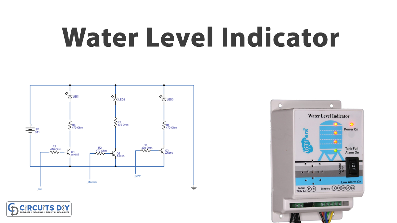
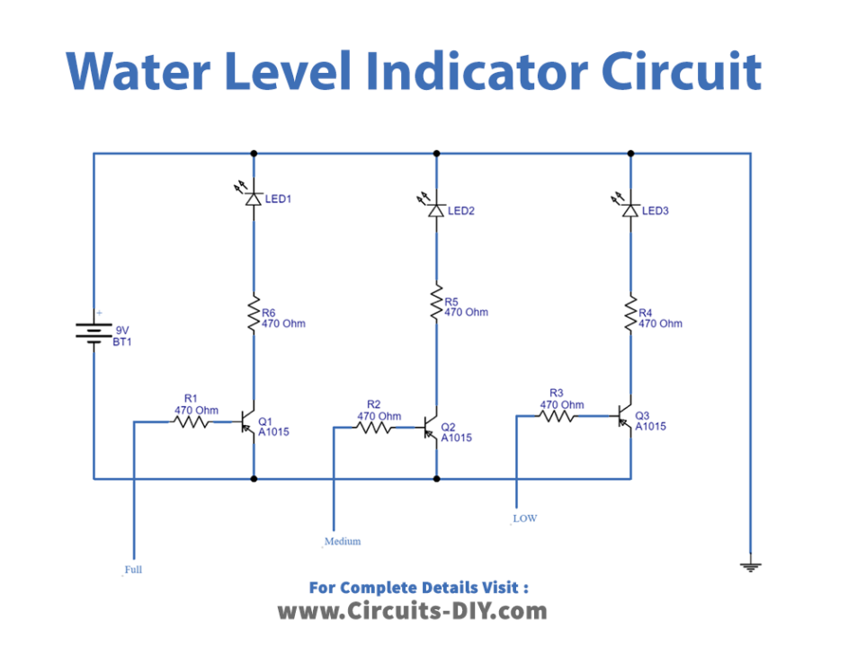
In this Simple water level indicator, we have used three PNP transistors. At the base of every transistor, we connected a wire through the 470 ohms resistor. The length of the wires is different according to the water level. Hence for the lower level, the length is greater. Whenever the water touches that wire, it triggers the base of the transistor, since we connected the LED at the collector terminal, hence the respective LED glows. So when the level of water is low, the first LED glows, at the medium level the second LED also turns ON, and at the full level LED 3 also starts glowing.
Application and Uses
- Oil tank level control systems.
- Automatic pumps.
- Industrial and home automation.
- Irrigation control systems, etc.