Introduction
Ever wondered when you travel to most countries at nighttime that how these street lights work? Ever admired those lights in the night and how they help to provide light and hence the way to people? Have you ever thought that how much it would be difficult if there would no street lights? And then think to try and make the circuit of this. So, in this article, we will assemble the street light circuit with a full explanation.
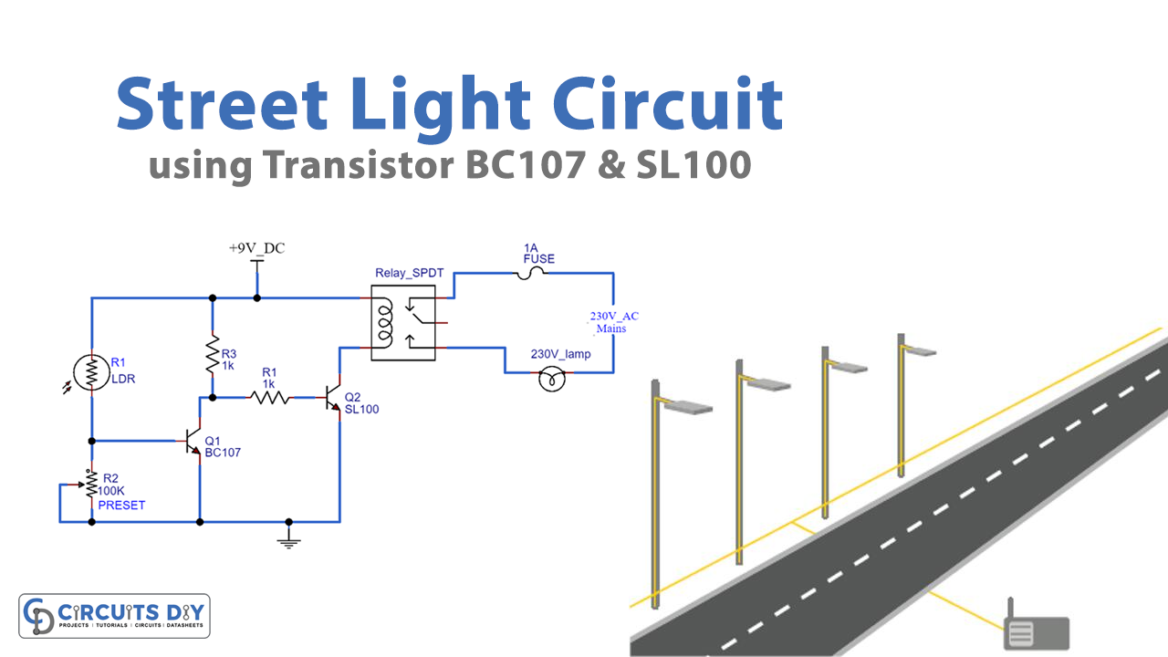
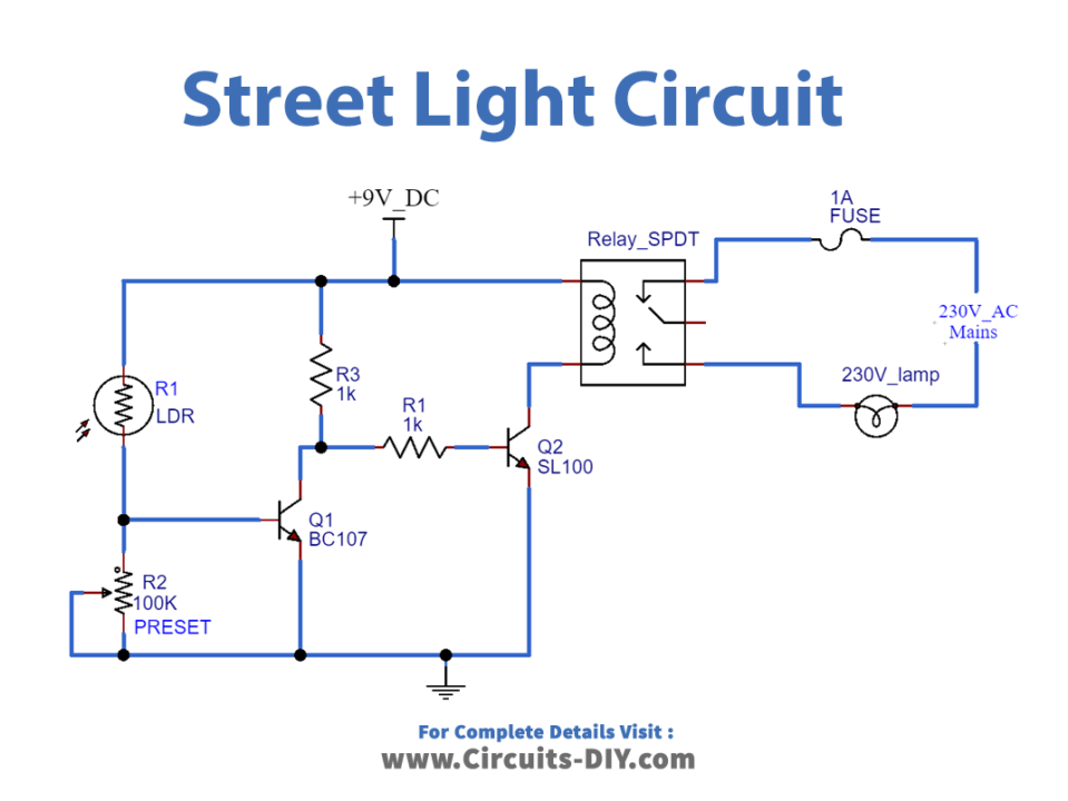
The street light circuit needs an LDR, a light-dependent resistor. A potentiometer to adjust the sensitivity of the circuit. The SPDT relay is 9 volts. And, a bulb has enough ratings of any watt. Power the circuit using the 9V DC supply.
Hardware Required
| S. No | Components | Value | Qty |
|---|---|---|---|
| 1. | Vero / PCB Board | – | 1 |
| 2. | Resistors | 1K | 2 |
| 3. | Potentiometer | 100K | 1 |
| 4. | Transistor | BC107, SL100 | 1, 1 |
| 5. | SPDT Relay | – | 1 |
| 6. | Fuse | – | 1 |
| 7. | Lamp | 230V | 1 |
| 8. | LDR | – | 1 |
Circuit Diagram
Working Explanation
At night day time the resistance is low. So, the voltage drop across the potentiometer is high. And, this turns ON the transistor Q1. The collector of transistor Q1 is connected to transistor Q2. Therefore, it turns OFF the relay. At nighttime when the resistance is higher. The voltage across the potentiometer decreases to 0.6 volts. And, the transistor Q1 gets OFF. Hence, the relay gets energized and turns ON the bulb.
Application and Uses
The main purpose of this circuit is to use it as a street light. But, it can be used as an intruder alarm, etc by doing some modification. The circuit can also be utilized in some LDR devices.