If you are looking for an easy and fun electronics project then this is it. In this tutorial, we are going to make a simple transistor code lock circuit. This circuit is inexpensive, simple, and gets the job done as well. It is using only a few components i.e. one transistor, 10 switches, two resistors, a relay along with a diode. Even though this circuit is using just a few basic components but it performs well and is perfect to make a code lock system in your house or office.
Hardware Components
The following components are required to make a One Transistor Code Lock Circuit
| S.no | Component | Value | Quantity |
|---|---|---|---|
| 1. | Input Supply DC | 5-12V | 1 |
| 2. | Switch | – | 10 |
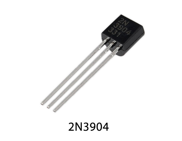
| 3. | Transistor | 2N3904 | 1 |
| 4. | Relays | – | 1 |
| 5. | Diode | 1N4007 | 1 |
| 6. | Resistor | 1.2KΩ | 2 |
2N3904 Pinout
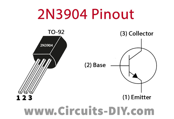
For a detailed description of pinout, dimension features, and specifications download the datasheet of 2N3904
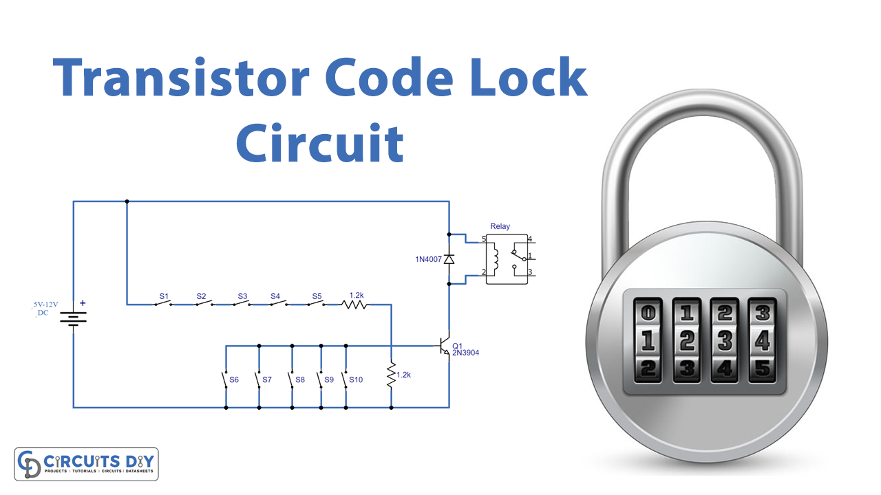
Transistor Code Lock Circuit
Working Explanation
The circuit is made up of a transistor switch. switches from S1 to S5 are connected in series between the base of the transistor and the positive supply whereas other switches S6 to S10 are connected in parallel across the base and the negative end of the supply. The working of this circuit is easy when the switches from S1 to S5 are turned on the relay will get the input signal and activates and when S6 to S10 are on the relay will remain inactive. Even if one switch from S1 to S5 will be off the relay will not activate. Points to be noted: After you are done with building the circuit, make sure to arrange the switch in a 0 to 9 keypad manner. You can either use a power supply or a battery to operate this circuit. The relay should have the same voltage as the power supply/operating voltage.
Applications and Uses
- Door locks
- Safety boxes
- Offices
- Jewelry boxes