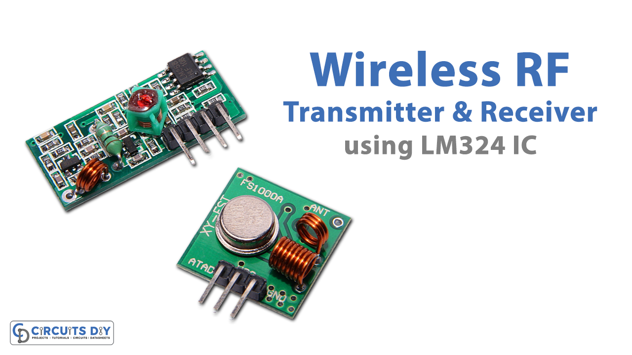
In this DIY, we demonstrate a Wireless RF Transmitter & Receiver with a Four-Level temperature Sensor Circuit. Wireless temperature sensors and monitors are well known these days in industrial and commercial applications as well as even in residential settings. A powerful wireless temperature sensor can likewise be worked with low-cost ICs and segments as appears in the circuit diagram below.
The project is very adaptable and can be customized for various temperature-related tasks. This wireless temperature sensor can detect four different temperature levels and send the data to the receiver. The four required levels of temperature can be chosen in the transmitting portion of the circuit and their outputs will be received at the receiving part. The outputs at the receiver can be utilized to drive LEDs to give a visual signal of the temperature level, a Buzzer, or alert to give a sound signal, or a relay switch to drive an apparatus, for instance, a cooling device, and so forth.
Hardware Components
The following components are required to make RF Transmitter Circuit
| S.no | Components | Value | Qty |
|---|---|---|---|
| 1 | IC | HT-12E | 1 |
| 2 | IC | LM324 | 4 |
| 3 | RF Module Transmitter | – | 1 |
| 4 | Transistor | 2N4401 | 4 |
| 5 | Antenna | 14 inch | 1 |
| 6 | Thermistor | 10K | 1 |
| 7 | Variable Resistor | 10K | 4 |
| 8 | Resistor | 1K, 8.2K, 750K | 4, 4, 1 |
| 9 | Battery | 5 – 10V | 1 |
LM324 Pinout
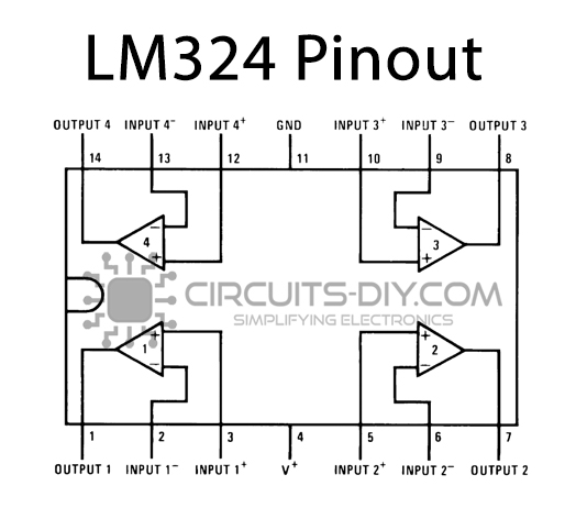
For a detailed description of pinout, dimension features, and specifications download the datasheet of LM324
RF Transmitter Circuit
Hardware Components
The following components are required to make RF Receiver Circuit
| S.no | Components | Value | Qty |
|---|---|---|---|
| 1 | IC | HT-12D | 1 |
| 2 | Transistor | BC337 | 4 |
| 3 | Diode | 1N4007 | 1 |
| 4 | RF Module receiver | – | 1 |
| 5 | Antenna | 14 inch | 1 |
| 6 | LED | – | 2 |
| 7 | Relay | – | 1 |
| 8 | Piezo Buzzer | – | 1 |
| 9 | Resistor | 1K, 33K | 6, 1 |
| 10 | Battery | 6v- 12v | 1 |
BC337 Pinout

For a detailed description of pinout, dimension features, and specifications download the datasheet of BC337
RF Receiver Circuit
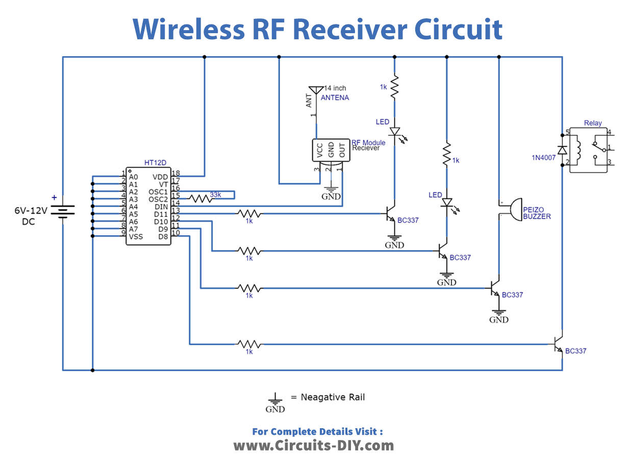
Circuit Operation
The project contains two parts which are a transmitter segment and a receiver segment. The four different required levels of temperature on which you need to turn the yield on the collector can be chosen with the 10K variable resistors utilized in the transmitter segment. The working voltage of the transmitter segment is 5V to 12V DC.
The working voltage of the receiver segment is 6V to 12V DC. The receiver segment of the undertaking has four outputs, two of them are associated with LEDs, one with a buzzer and one with a relay switch, yet you can likewise utilize transfers in the spot of LEDs and buzzer.
Applications and Uses
Most commonly, temperature sensors are utilized to measure temperature in circuits that control an assortment of equipment.