From providing a bass its satisfying crunch to boosting signals in ham radios so that the broadcasts can be enjoyed around the globe, audio amplifiers are an integral component of any device that reproduces sound signals. Simply put, an Audio amplifier is a small electromagnetic device that boosts an input sound signal & delivers this amplified audio signal to an audio transducer such as a loudspeaker. With the increasing trend of wireless technology & its implied convenience. The demand for new & improved wireless speakers/Audio amplifiers is ever-increasing. So in today’s tutorial, we will design a simple Wireless Speaker Audio Amplifier Using a 2SC2625 Power Transistor.
The heart of this Wireless Speaker Audio Amplifier is a 2SC2625 Power transistor. 2SC2625 is a High Voltage High-Speed Switching Transistor. It is an NPN transistor in a TO-39 packaging, offering a max collector-base voltage of 450V & a collector current dissipation of 80W, so use an appropriate heat sink during transistor operation.
JLCPCB is the foremost PCB prototype & manufacturing company in china, providing us with the best service we have ever experienced regarding (Quality, Price Service & Time).
Hardware Required
The following components are required to make Wireless Speaker Audio Amplifier Project
| S.no | Component | Value | Qty |
|---|---|---|---|
| 1. | Power transistor | 2SC2625 | 1 |
| 2. | Loudspeaker | 8Ohms | 1 |
| 3. | Enameled Copper wire | – | 3-4 meters |
| 4. | Heatsink | – | 1 |
| 5. | Audio Jack | 3.5mm/male | 1 |
| 6. | Cement Resistor | 5W/150K | 1 |
| 7. | Resistor | 680Ohms | 1 |
| 8. | Capacitor | 47uF/10V | 1 |
| 9. | Soldering Iron | 45W – 65W | 1 |
| 10. | Soldering Wire with flux | – | 1 |
| 11. | Veroboard | – | 1 |
| 12. | DC Battery | 12V | 1 |
| 13. | Connecting Wires | – | As per need |
2SC2625 Pinout
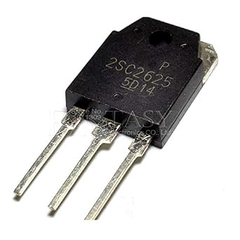
For a detailed description of pinout, dimension features, and specifications download the datasheet of 2SC2625
Useful Steps
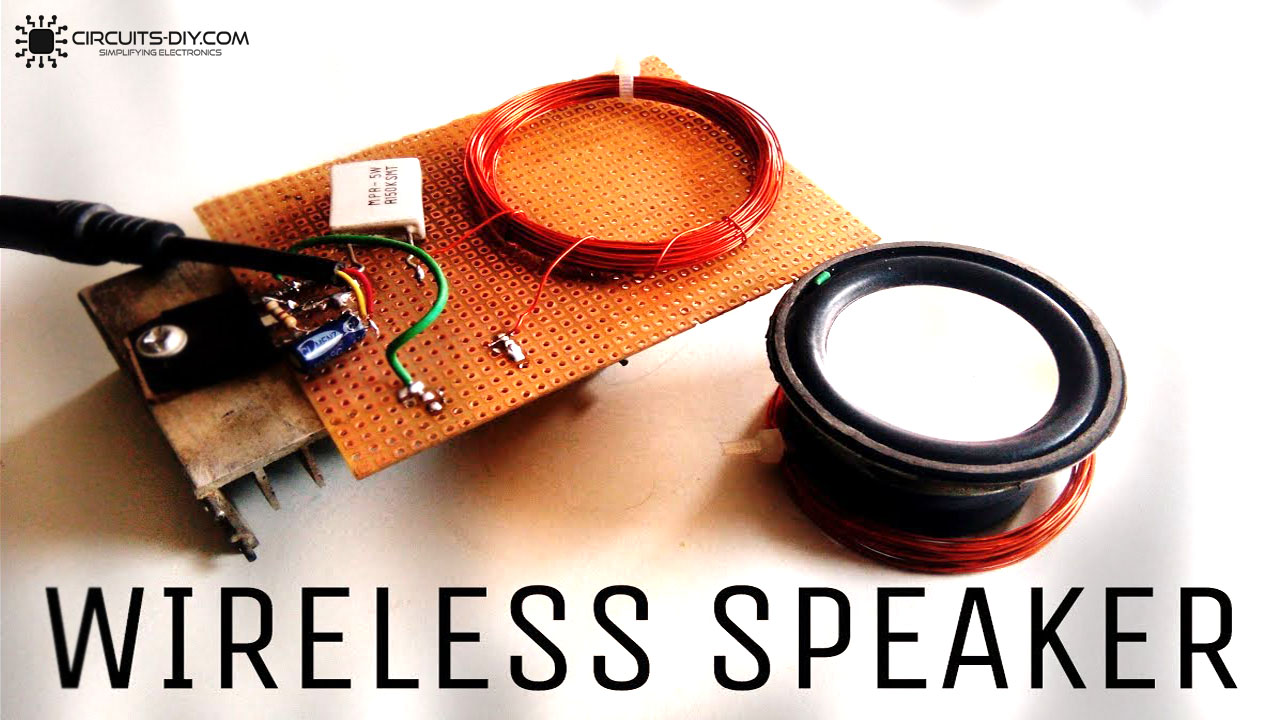
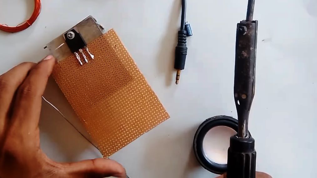
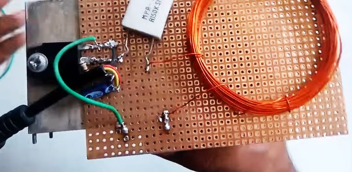
1) Screw on the 2SC2625 transistor on the heat sink. After that solder the transistor on the Veroboard.
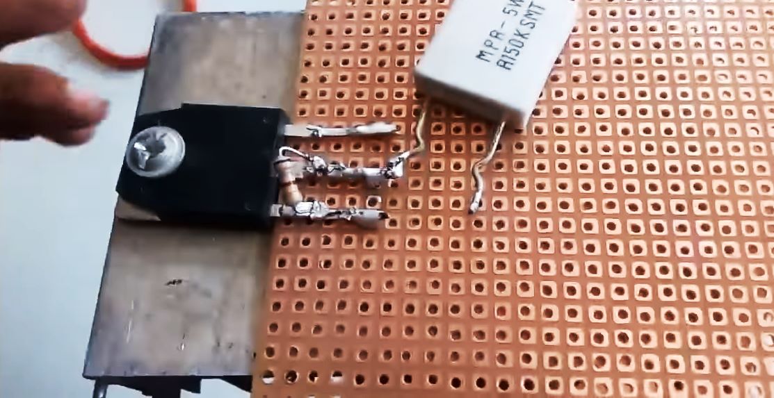
2) Solder the collector terminal of the transistor with the 5W cement resistor. After that, solder the 680 Ohm resistor between the collector – base terminal of the transistor.
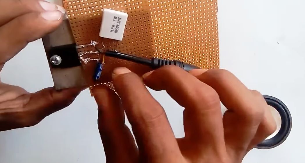
3) Solder the 47uF capacitor between the collector terminal of the transistor & the +ve terminal of the DC audio jack.
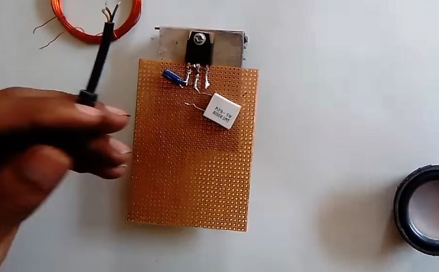
4) Solder the -ve terminal of the DC audio jack with the GND of the circuit.
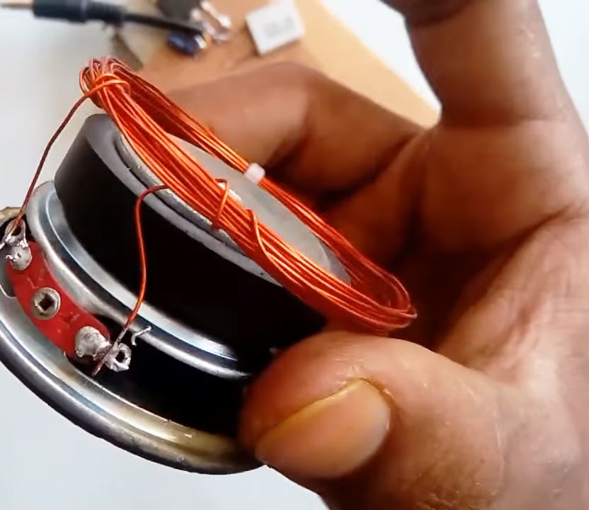
5) Make a pair of coiled enameled copper wires (40 turns for one & 25 turns for the other). Solder the 25 turns with the -ve & +ve terminal of the 8Ohm speaker.
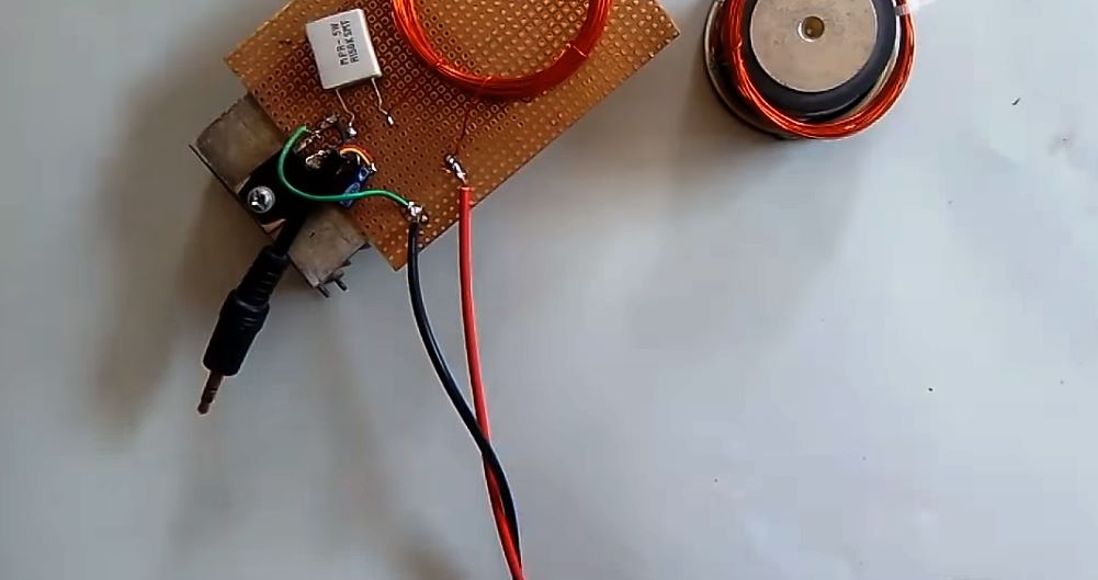
6) Solder the 40-turn coil with a 5W cement resistor. After that, solder the +ve terminal of the 12V DC Battery with 40 turn coil & the -ve with the emitter terminal of the transistor.
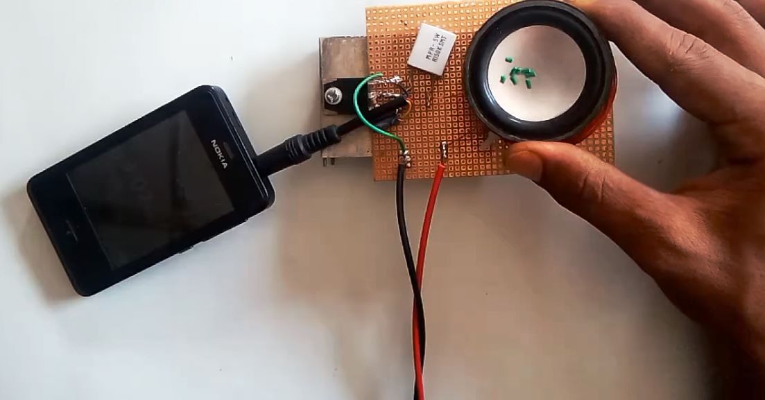
7) Plug in the 3.5mm Audio jack to a device such as a mic or smartphone. Now, power up & test the circuit.
Wireless Speaker Amplifier Circuit
Working Explanation
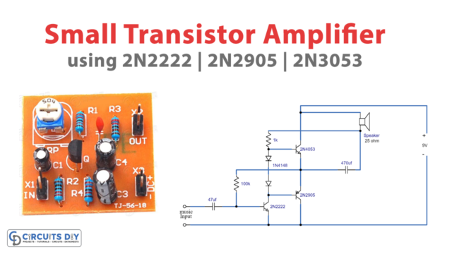
The working of this circuit is as follows, an audio input is taken from a device such as a smartphone/PC by using an audio jack. this audio signal acts as a control signal on the base of the 2SC2625 transistor. Here, a coupling capacitor (47uF) is used, this blocks the DC component of the input audio signal, allowing only the AC part of the signal to pass through.
The collector output then goes through a cement resistor. Here we are using a 5W ceramic cement resistor to achieve a proper value of induction in the 40-turn enameled copper coil. Now, the 40-turn coil is brought near the 25-turn coil connected to the 8 Ohm speaker. The Audio output from the transistor is then electromagnetically connected with the speaker through the step-down mutual induction of the two coils. Always use a heat sink of proper thickness with the power transistor to compensate for the exceptional power losses.
Applications
- Mainly used in devices such as interactive toys, Robots & Hi-Fi devices.
- Widely used in sound systems such as speakers, high-power megaphones, & acoustic systems.