We all know that water level indicators are very important and useful, in this tutorial we are making an enhanced version of a wireless water level indicator/sensor using an RF module. Without using a microcontroller, the maximum transmitting range of the circuit is up to 100 meters. This circuit is more reliable, stable, and designed to consume low power by adding the encoder and decoder ICs. Because of these ICs, this circuit can be modified and used for a lot of applications.
The transmitter circuit is placed high above the ground level or far away from the receiver and changing the batteries can become a hassle therefore this circuit is designed in such a way that it consumes less current. Now it only consumes 370µA current in standby mode and the batteries will last for several months, this reduces the operating cost too.

Hardware Components
The following components are required to make the Transmitter and Receiver circuit for the project Wireless Water Level Indicator
| S.no | Component | Value | Qty |
|---|---|---|---|
| 1. | Input Supply DC | 5-12V, 5-6V | 1, 1 |
| 2. | IC | HT-12E, HT-12D | 1 |
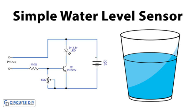
| 3. | Transistor | BC337, 2N3904, 2N2222 | 3, 1, 1 |
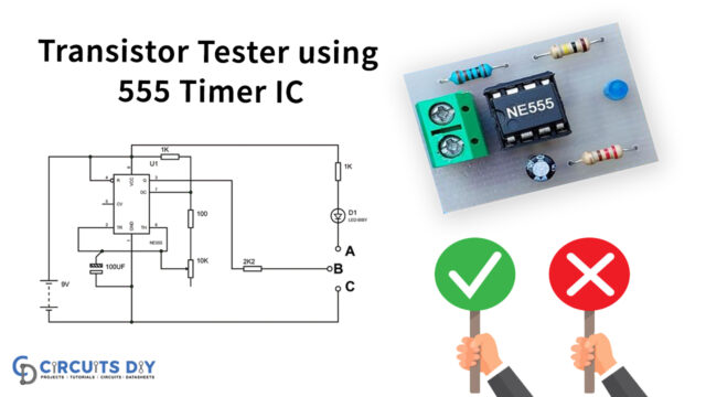
| 4. | IC | NE7555, NE555 Timer | 1, 1 |
| 5. | RF Module (transmitter & receiver) | – | 1 |
| 6. | Antenna | 14 inch | 2 |
| 7. | Resistor | 1KΩ,270KΩ,4.7KΩ,1MΩ,750KΩ,33KΩ | 5,1,2,1,1,1 |
| 8. | Variable Resistor | 100KΩ | 2 |
| 9. | Electrolytic Capacitor | 10µF, 100uF | 1 |
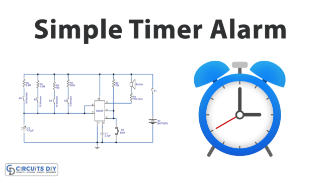
| 10. | Piezo buzzer | – | 1 |
| 11. | Ceramic Capacitor | 0.01µF, 0.1uF | 1, 2 |
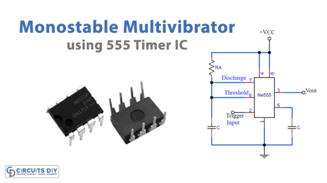
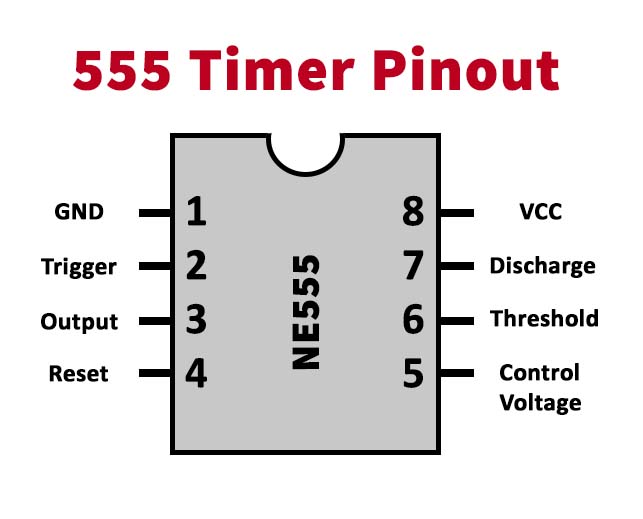
NE555 IC Pinout

For a detailed description of pinout, dimension features, and specifications download the datasheet of 555 Timer
7555 Pinout
HT-12D Pinout

HT-12E Pinout

Wireless Water Level Indicator Circuit
Working Explanation
This circuit is divided into two circuits one is a transmitter circuit and the second is a receiver circuit. we will explain the working of both of them separately.
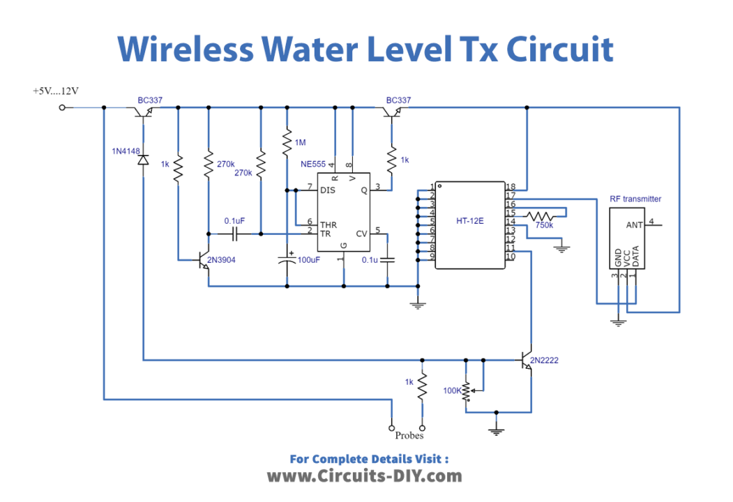
Transmitter Section
The transmitter section has a CMOS 7555 timer IC, the transmitter part of the module, an HT-12E encoder IC, four transistors, and a few other discrete components. The probes are used for sensing purposes, they are placed at the required level of water. When the water reaches that level it touches the probes and these probes will send an input signal to the circuit. now the transmitter sends the signals to the atmosphere for 5 to 10 minutes, this time period is preset and can be increased or decreased by using a higher or lower value of the capacitor Cx. The maximum range of the circuit is achieved by providing 12V to the transmitter circuit.
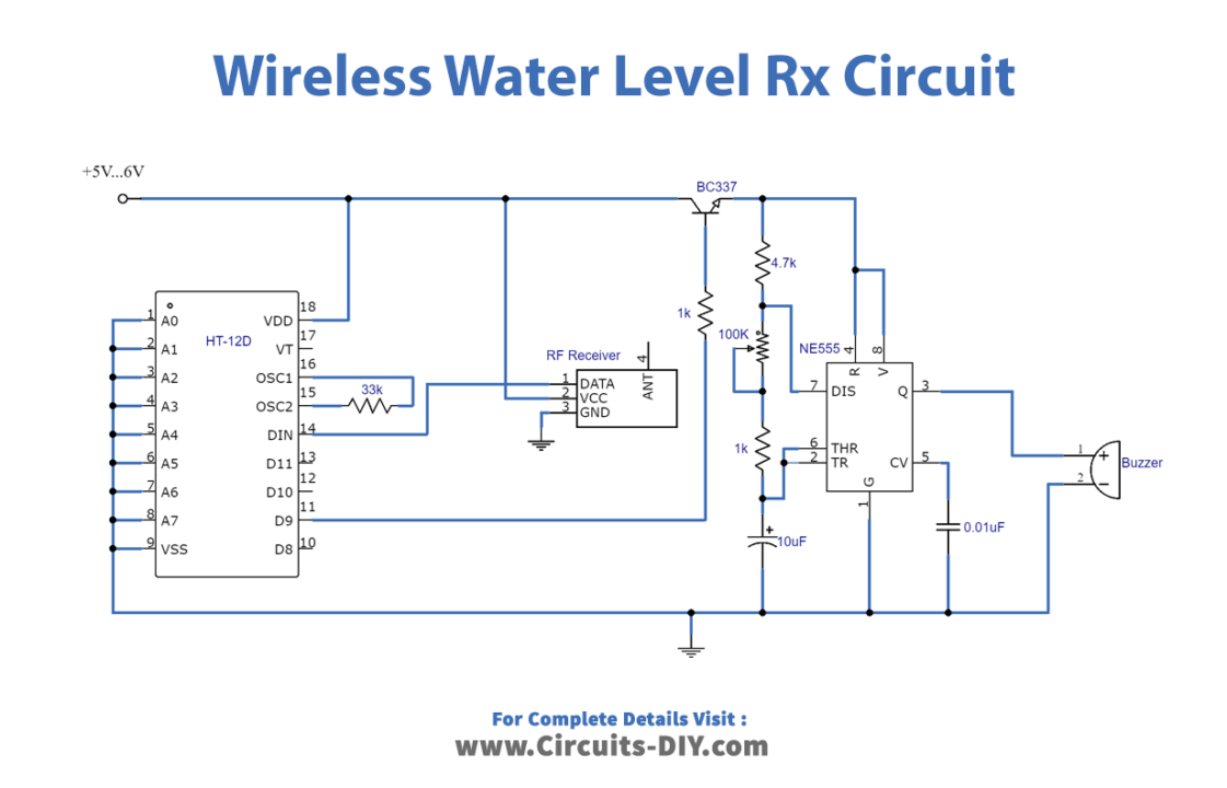
Receiver Section
The receiver section has an HT-12D decoder IC, 555 timer IC, RF receiver part of the RF module, buzzer, and a few other discrete components. On receiving the signals from the transmitter it will activate the circuit and the buzzer will produce beep sounds for indication. The frequency of these beeps can be adjusted by the 100K variable resistor.