Introduction
We know that voltage regulators offer controlled output voltage and are commonly employed in embedded systems when we talk about them. A regulated power supply, for example, ensures that the output does not vary when the input signals change. To put it another way, the outcome is consistent and independent of the input. In this tutorial, we are going to make a “12 Volt Regulated power supply circuit using Zener diode”.
In the making of the circuit, we are employing a Zener diode. A Zener diode permits current to flow not just from anode to cathode, but also in the opposite direction when it reaches the Zener voltage. Zener diodes are the most widely used semiconductor diodes because of their feature.
Hardware Components
The following components are required to make a 12V Power Supply Circuit
| S.no | Component | Value | Qty |
|---|---|---|---|
| 1. | Transformer | 0-15V AC | 1 |
| 2. | Diode | 1N4007 | 4 |
| 3. | NPN Power Transistor | 2SC1061 | 1 |
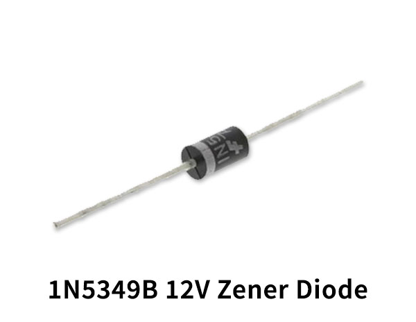
| 4. | Zener Diode | 12V | 1 |
| 5. | LED | – | 1 |
| 6. | Electrolyte Capacitor | 100uF, 470uF | 2, 1 |
| 7. | Resistor | 1KΩ, 10Ω, 560Ω | 1, 1, 1 |
| 8. | Battery | 12v |
2SC1061 Pinout
For a detailed description of pinout, dimension features, and specifications download the datasheet of 2SC1061
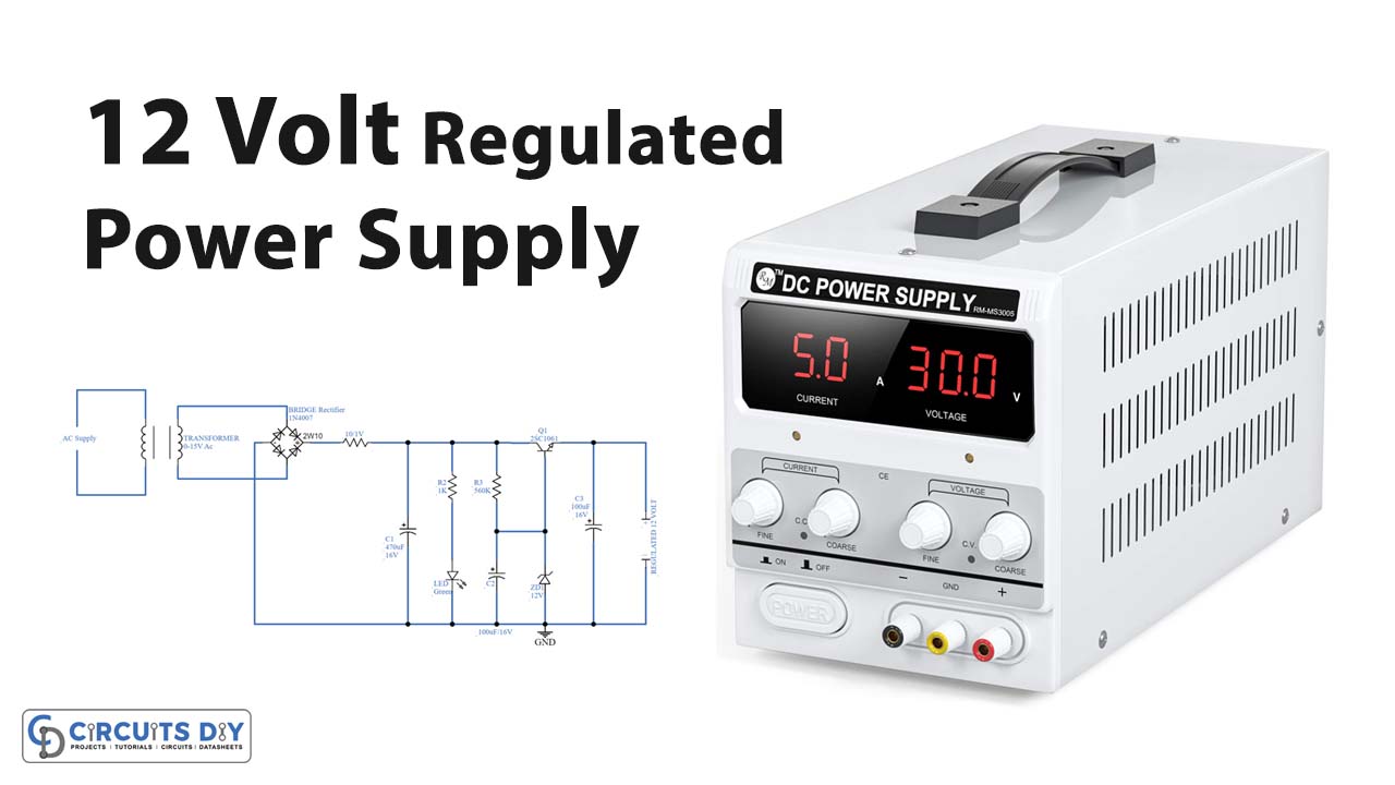
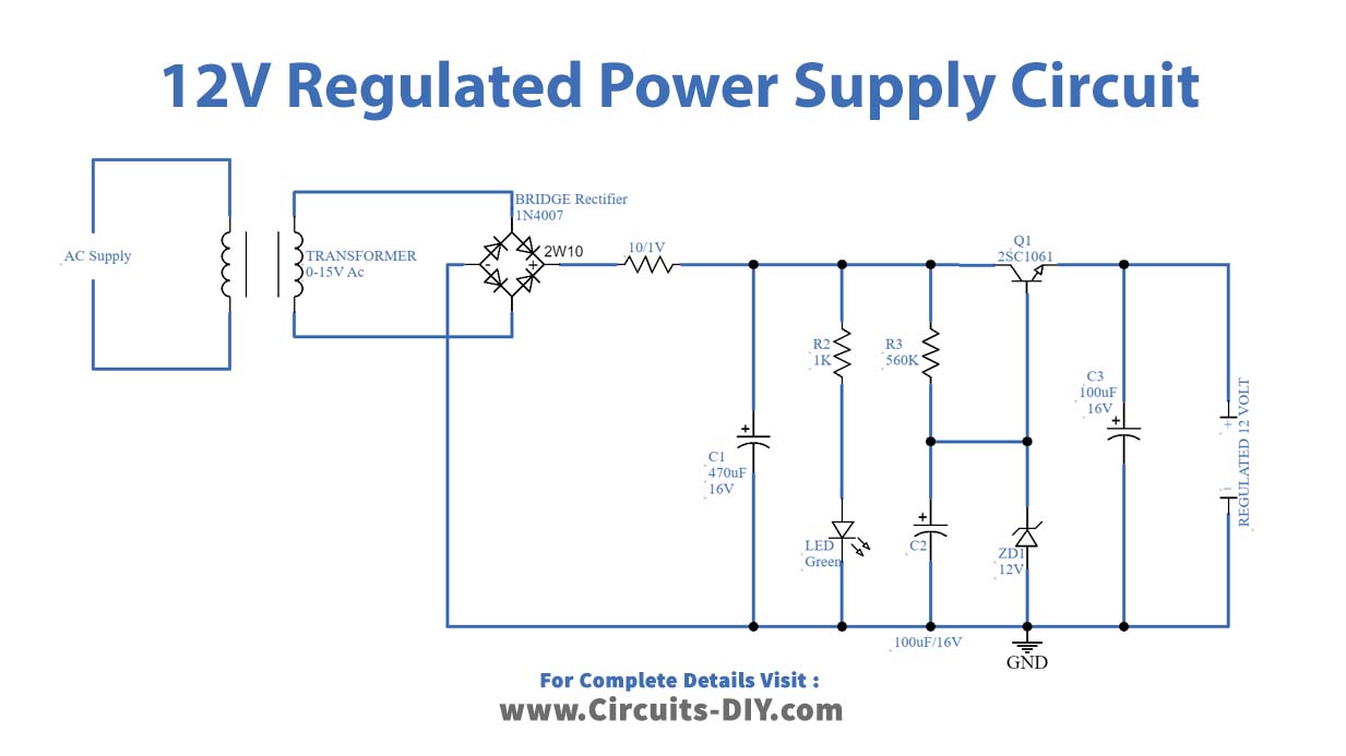
12V Power Supply Circuit
Working Explanation
In this 12 Volt Regulated power supply circuit, we are first using the step-down transformer, the step-down transformer lowers the AC voltage to 15 volts. Then four 1N4007 diodes are used as bridge rectifiers to provide a regulated DC supply. This DC will get filtered using a C1 capacitor, and then the filtered DC is supplied through a 12v Zener diode, which breaks down the DC supply to 12v. The output load is driven by the transistor 2sc1061.
Application and Uses
Voltage regulators can be used to power sensors, operational amplifiers, and other electronic components and devices that require both regulated voltages.