Introduction
A 3-phase signal generator circuit is a powerful tool for any engineer or technician working in electrical and electronic systems. This circuit can produce a precise and stable three-phase signal, which can be used for various applications such as testing and calibrating power electronics devices, motors, and generators.
With the ability to generate a variety of waveforms, such as sine, square, and triangle, this circuit is a versatile and valuable asset for any electrical or electronic testing and troubleshooting needs. Its ability to generate a stable 3-phase signal is a must-have for any engineer, technician, or hobbyist dealing with power electronics, motor, and generator testing.
What is 3 Phase Signal Generator?
A 3 Phase Signal Generator Circuit is an essential device in electrical engineering. It generates accurate and stable electrical signals for testing and measuring equipment and for controlling and synchronizing power systems. The 3 Phase Signal Generator Circuit is a versatile tool that allows engineers and technicians to test and calibrate equipment and monitor and control power systems in real-time.
Components Required
You will require the following hardware for 3-Phase Signal Generator Circuit.
| S.no | Component | Value | Qty |
|---|---|---|---|
| 1. | Transistor | BC547 | 3 |
| 2. | Resistor | 10k | 3 |
| 3. | Capacitor | 1u | 3 |
| 4. | Resistor | 2K2 | 2 |
| 5. | On/Off switch | – | 1 |
| 6. | Power supply | – | 1 |
Steps to Build a 3-phase Signal Generator Circuit
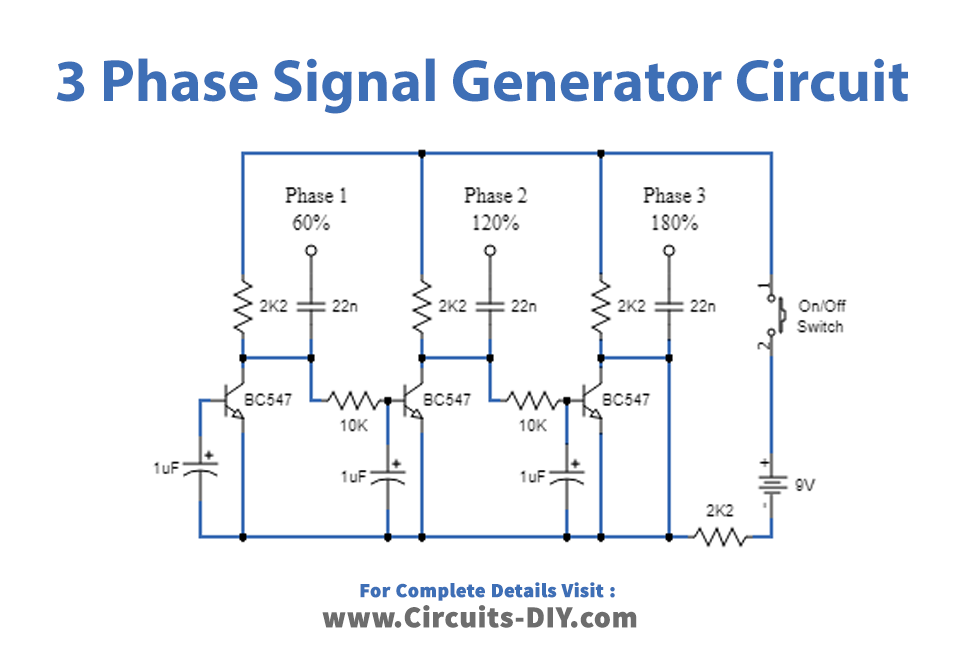
You need to follow the given circuit diagram and connections to make this circuit:
Circuit Diagram
Connections
- Three BC547 transistors (Q1, Q2, Q3) are set up in a cross-coupled configuration.
- A parallel RC timing constant is connected across the base of each transistor. The resistor (10k) and capacitor (1u) values are the same for each transistor.
- The collector of Q1 is connected to the base of Q2, the collector of Q2 is connected to the base of Q3, and the collector of Q3 is connected to the base of Q1.
- The emitters of all the transistors are connected to the ground.
- A 2K2 resistor is connected in series with the base of Q1.
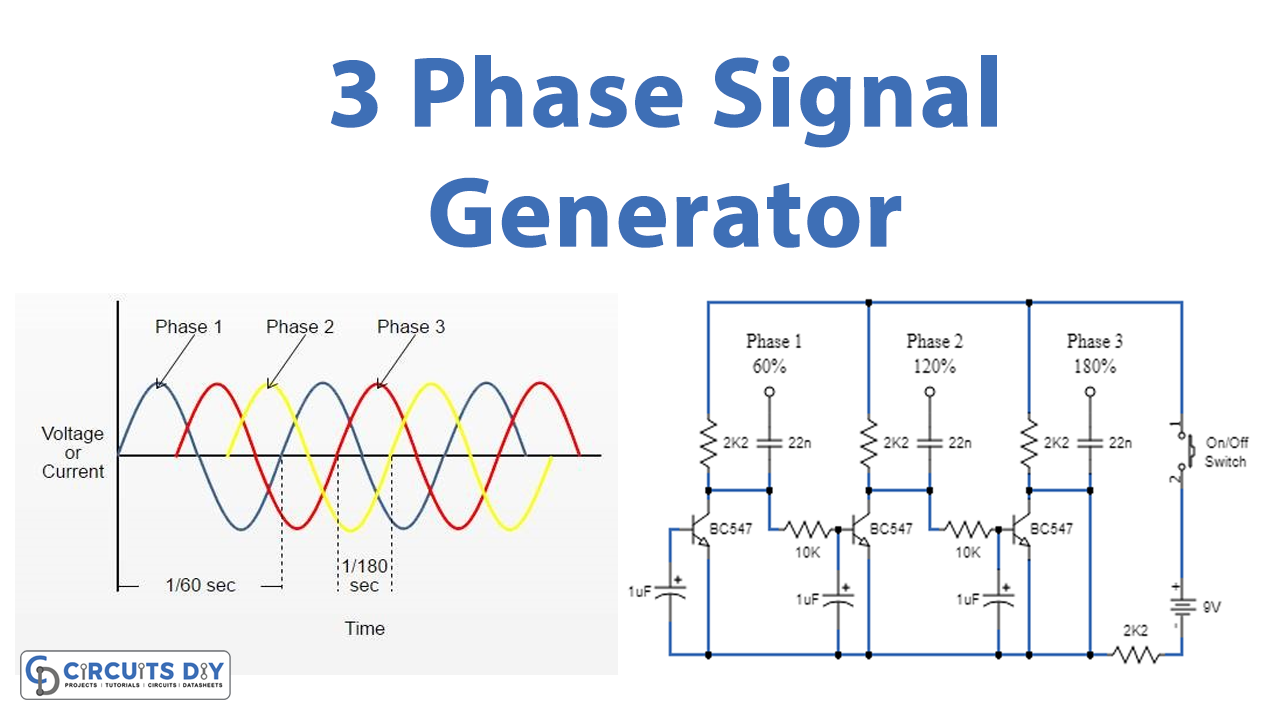
- The collectors of Q1, Q2, and Q3 are the output terminals of the circuit, providing the three-phase signal pattern with a 120-degree phase shift.
- The power supply is applied to the circuit.
Working Explanation
When power is applied, the phases may appear to go through a locked sequence. Still, due to slight variations in the values of the capacitors, one of them will charge up first, initiating sequential conduction across the transistors. For example, suppose the middle transistor base capacitor charges up first. In that case, it allows the middle transistor to conduct first, which grounds the base of the extreme right transistor, preventing it from conducting at that moment. However, simultaneously, the base capacitor of the left or the right transistor also gets charged, which forces the middle transistor to turn off and enables the right transistor to conduct.
This mutual push-pull process results in a constant sequential train of conduction across the transistors, creating the intended three-phase signal pattern across the collectors of the transistors. The circuit design of the capacitors is such that the resulting signal shape is a pure sine wave.
The 2K2 resistor plays a critical role in initiating the 3-phase signal generation process. Without this resistor, the circuit may stall unexpectedly. The degree of phase shift can be adjusted by changing the RC values across the bases of the transistors. In this circuit, it is set to generate a 120-degree phase shift.
Final Words
In conclusion, building a 3-phase signal generator circuit can be a challenging task. Still, with the proper knowledge and components, it is possible to create a functional and efficient driver circuit. If you have any queries or comments, please feel free to reach out. Thank you for reading!