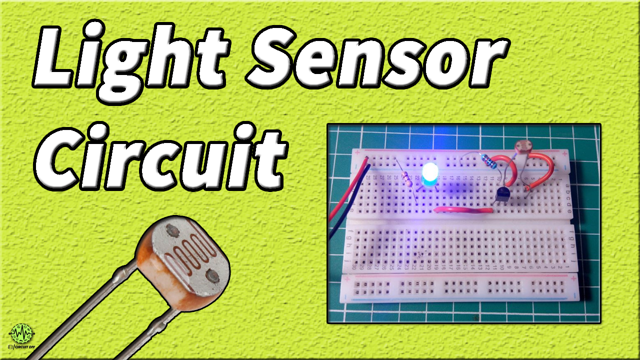
The light sensor circuit is one of the coolest circuits in basic electronics projects. It detects the quantity of light present in the environment and the results can be detected by the brightness of the LED. This circuit may be useful for knowing the working of LDR (Light Dependent Resistor) or Photoresistor, the working of NPN Transistor, and the impact of the sensitivity of the resistor on the circuit. These types of circuits are useful when we need to know the presence and absence of lights on the premises.
Uses of Light sensor circuits are in the industry as well as Commerical and non-commercial areas. We can save power in and outside the premises by using this circuit. Street lights are glowing in the daytime by negligence so we can control these lights accordingly. Lights sensors can also detect light that is not visible by the human eye like x-rays.
Hardware Components
The following components are required to make Light Sensor Circuit
| S. NO | Component | Value | Qty |
|---|---|---|---|
| 1. | Breadboard | – | 1 |
| 2. | Connecting Wires | – | 1 |
| 3. | Battery | 9v | 1 |
| 4. | Resistors | 10K, 470 ohms | 1, 1 |
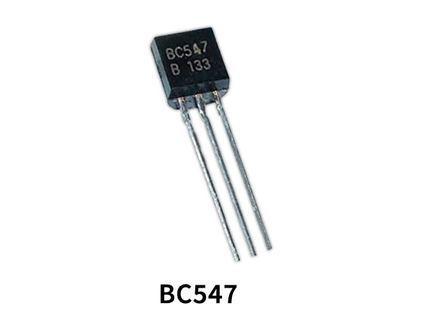
| 5. | NPN Transistor | BC547 | 1 |
| 6. | LED | 5mm | 1 |
| 7. | LDR | – | 1 |
BC547 Pinout
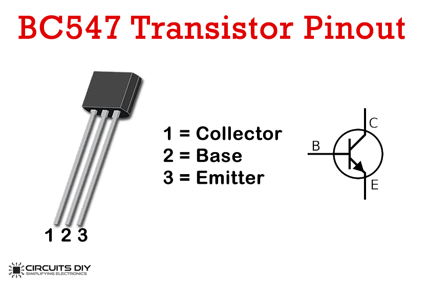
For a detailed description of pinout, dimension features, and specifications download the datasheet of BC547
Light Sensor Circuit
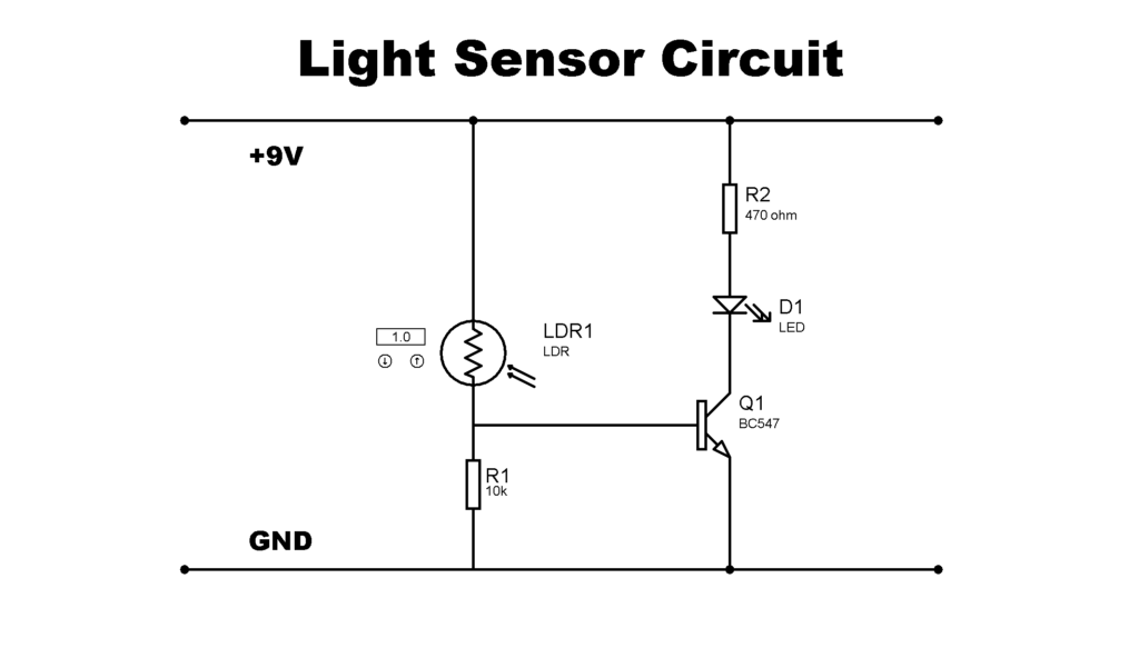
Working Explanation
We make three conditions for an explanation of circuits which is as follows
- Full Light
- Medium Light
- No Light
For the first condition when we power up the circuit, light incident on LDR has minimized the resistance due to this minimum voltage drop at the base of the transistor and very dim light glow. For the second condition medium-light incident on LDR due to which a medium brightness of LED glow and for the third condition very low light incident on LDR, the result of this is LED glow with Full Brightness. The brightness of the LED can be adjustable by varying the resistance connected at the base of the transistor.
Useful Steps
Firstly connect LDR on Breadboard then connect the base of BC547 to one pin of LDR. On the other end connect an LED to two parallel pins of Breadboard. Now a resistor of 470 Ohm needs to be connected to the +ve terminal of LED to the +ve rail of the Breadboard and the second resistor of 10K ohm needs to be connected to the base of the transistor to the -ve rail of the breadboard. Now connect jumpers between the -ve terminal of the LED to the collector pin of the transistor and from the emitter of the transistor to the -ve rail of Breadboard and from the remaining LDR pin to the +ve rail of BreadBoard. Finally, connect a battery to the Breadboard and test the circuit.
Application of Light Sensor Circuit
Some applications are as below
- Burglar alarm circuits
- Alarm clock
- Light intensity meter