Introduction
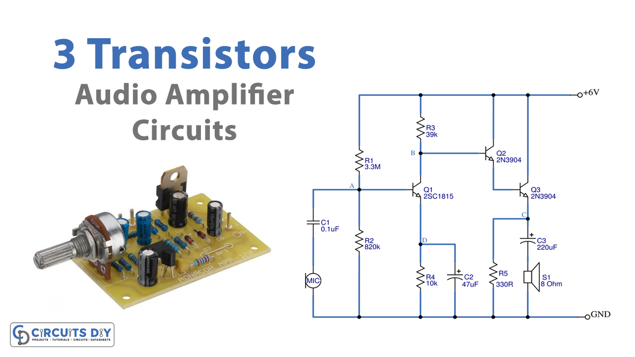
In this tutorial, Let’s try the 3 transistors Audio Amplifier circuits (MONO). Here, we are going to use three transistors to amplify a single giving audio input signal. Using a transistor, not only benefits amplification but also helps to reduce the size of the circuit, because a transistor takes very less area, as compared to integrated circuits. So, in the making of the circuit, we are using two types of transistors, 2N3904, and 2SC1815. So before starting to build the circuit, let’s take a look at their features.
2N3904 Features
- Bi-Polar NPN Transistor
- DC Current Gain (hFE) is 300 maximum
- The continuous Collector current (IC) is 200mA
- Base- Emitter Voltage (VBE) is 6V
- Collector-Emitter Voltage (VCE) is 40V
- Collector-Base Voltage (VCB) is 60V
2SC1815 Features
- General Purpose NPN Transistor
- DC Current Gain (hFE) 70 to 700
- The continuous Collector current (IC) is 150mA
- Collector-Emitter voltage (VCE) is 50V
- Collector-Base voltage (VCB) is 60V
- Emitter-base breakdown voltage (VEBO): 5V
- Collector-emitter saturation voltage drop (VCE): 0.25V
Hardware Required
| S.no | Component | Value | Qty |
|---|---|---|---|
| 1. | Transistor | 2N3904 , 2SC1815 | 2,1 |
| 2. | Resistor | – | 1, 1, 1, 1, 1 |
| 3. | Capacitor | 0.1uF, 47uF, 220uF | 1, 1, 1 |
| 4. | Speaker | 8 0hm | 1 |
| 5. | MIC | – | 1 |
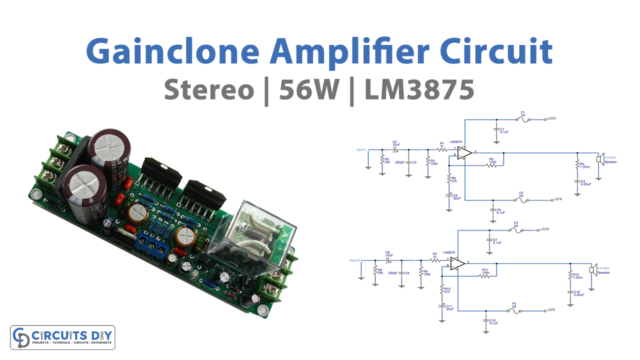
Circuit Diagram
Working Explanation
In this 3 Transistors Audio Amplifier Circuit, first, the audio signal is fed into the circuit through mic 1. It is then converted into a tiny electrical signal that is sent to Q1 at point A. First, to amplify the signal we have configured a common emitter. Resistors R1 and R2 are used to divide the voltage into bias to transistor Q1. However, the signal is insufficient at point B. Therefore, it is transferred to transistors Q2 and Q3, to amplify the signal so that it would be able to be driven into the speaker.
Application Uses
- In mic, speaker audio applications