Overview
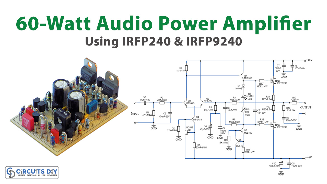
In honor of the one-hundredth design published on this website and in response to numerous requests for a more potent amplifier than the 25W MOSFET model, we present a 60 – 90W High-Quality power amplifier design. In today’s tutorial, we are going to make a “60 Watt Audio Power Amplifier” using IRFP240 and IRFP9240 HexFETs.
What is HexFET?
A HexFET is a type of field-effect transistor (FET) that uses a hexagonal structure for its gate electrode. These transistors are commonly used in power management applications due to their high efficiency and low power consumption. The “Hex” in HexFET refers to the hexagonal layout of the gate structure, while “FET” stands for field-effect transistor, which is a type of semiconductor device used for controlling the flow of electrical current in electronic circuits.
The circuit topology remains largely unchanged from the aforementioned amplifier, but we’ve incorporated the highly durable IRFP240 and IRFP9240 MosFet devices as the output pair, along with Motorola’s renowned high-voltage transistors in the initial stages.
The supply rails’ voltage has been conservatively set at a relatively low + and – 40V. For those interested in experimentation, the supply rails’ voltage can be increased to a maximum of + and – 50V, allowing the amplifier to approach the 100W into 8 Ohm target. Feel free to explore! Additionally, we offer a complementary Modular Preamplifier design utilizing discrete components: Modular Audio Preamplifier.
Hardware Components
To make a 60-watt Audio Power Amplifier, you’ll need the following hardware components to get started:
| S.no | Components | Value | Qty |
|---|---|---|---|
| 1 | Transistors | Q1,Q2,Q4=MPSA43 200V 500mA Q3,Q5=BC546 65V 100mA Q6=MJE340 200V 500mA NPN Transistor Q7=MJE350 200V 500mA PNP Transistor Q8=IRFP240 200V 20A N-Channel Hexfet Transistor Q9=IRFP9240 200V 12A P-Channel Hexfet Transistor | 3 2 1 1 1 1 |
| 2 | Capacitors | C1=470nF 63V Polyester Capacitor C2=470pF 63V Polystyrene or ceramic Capacitor C3=47µF 63V Electrolytic Capacitor C4,C8,C9,C11=100nF 63V Polyester Capacitors C5=10pF 63V Polystyrene or ceramic Capacitor C6=1µF 63V Polyester Capacitor C7,C10=100µF 63V Electrolytic Capacitors | 1 1 1 1 1 1 1 |
| 3 | Diodes | D1=1N4002 100V 1A | 1 |
| 4 | Resistors | R1=47K 1/4W Resistor R2=4K7 1/4W Resistor R3=22K 1/4W Resistor R4=1K 1/4W Resistor R5,R12,R13=330R 1/4W Resistors R6=1K5 1/4W Resistor R7=15K 1/4W Resistor R8=33K 1/4W Resistor R9=150K 1/4W Resistor R10=500R 1/2W Trimmer Cermet R11=39R 1/4W Resistor R14,R15=R33 2.5W Resistors R16=10R 2.5W Resistor R17=R22 5W Resistor (wirewound) | 1 1 1 1 3 1 1 1 1 1 1 3 1 2 |
| 5 | LEDs | D2=5mm. Red LED | 1 |
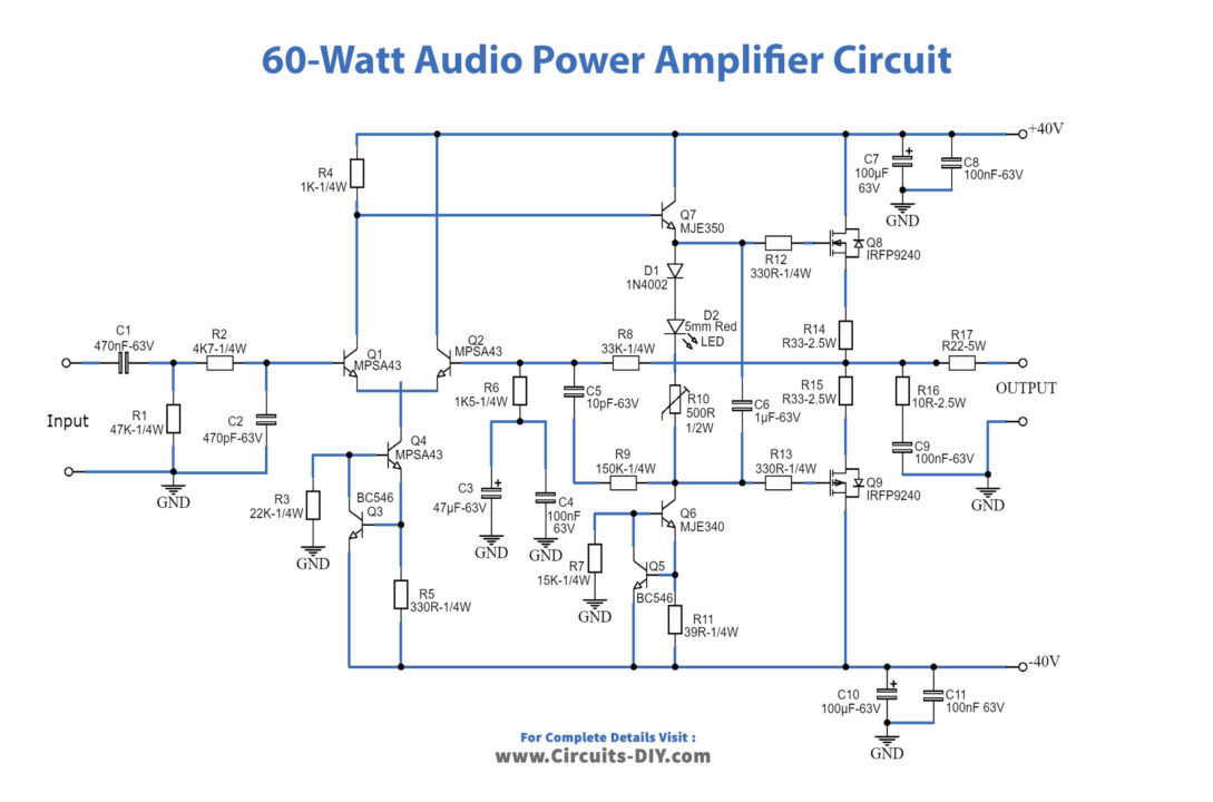
Schematic
Power Supply Schematic

In the original circuit, a three-diode string was connected in series with R10. To enhance quiescent current stability across a wider temperature range, two of these diodes have been replaced with a red LED. This modification was suggested by David Edwards from LedeAudio.
A small U-shaped heatsink is required for Q6 and Q7, while Q8 and Q9 need to be mounted on larger heatsinks.
To measure quiescent current, use an Avo-meter connected in series with the positive supply rail with no input signal. Adjust the Trimmer R10 to its minimum resistance, power on the amplifier, and adjust R10 until a current draw of approximately 120 – 130mA is reached. Wait for about 15 minutes, observe any current variations, and readjust if necessary.
The suggested values for C1 and C2 in the Power Supply Parts List are the minimum for a mono amplifier. For better performance, especially in stereo setups, consider increasing these values; 10000µF is a reasonable compromise.
Proper grounding is crucial to eliminate hum and ground loops. Connect the ground sides of R1, R3, C2, C3, and C4, along with the ground input wire, to the same point. Connect R7 and C7 to C11 for the output ground. Finally, separately connect the input and output grounds to the power supply ground.
Specifications
| Output power: | 60 Watt RMS @ 8 Ohm (1KHz sinewave) – 90W RMS @ 4 Ohm |
| Sensitivity: | 1V RMS input for 58W output |
| Frequency response: | 30Hz to 20KHz -1dB |
| Total harmonic distortion @ 1KHz: | 1W 0.003% 10W 0.006% 20W 0.01% 40W 0.013% 60W 0.018% |
| Total harmonic distortion @10KHz: | 1W 0.005% 10W 0.02% 20W 0.03% 40W 0.06% 60W 0.09% |
| Stability: | Unconditionally stable on capacitive loads |