Introduction
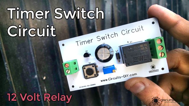
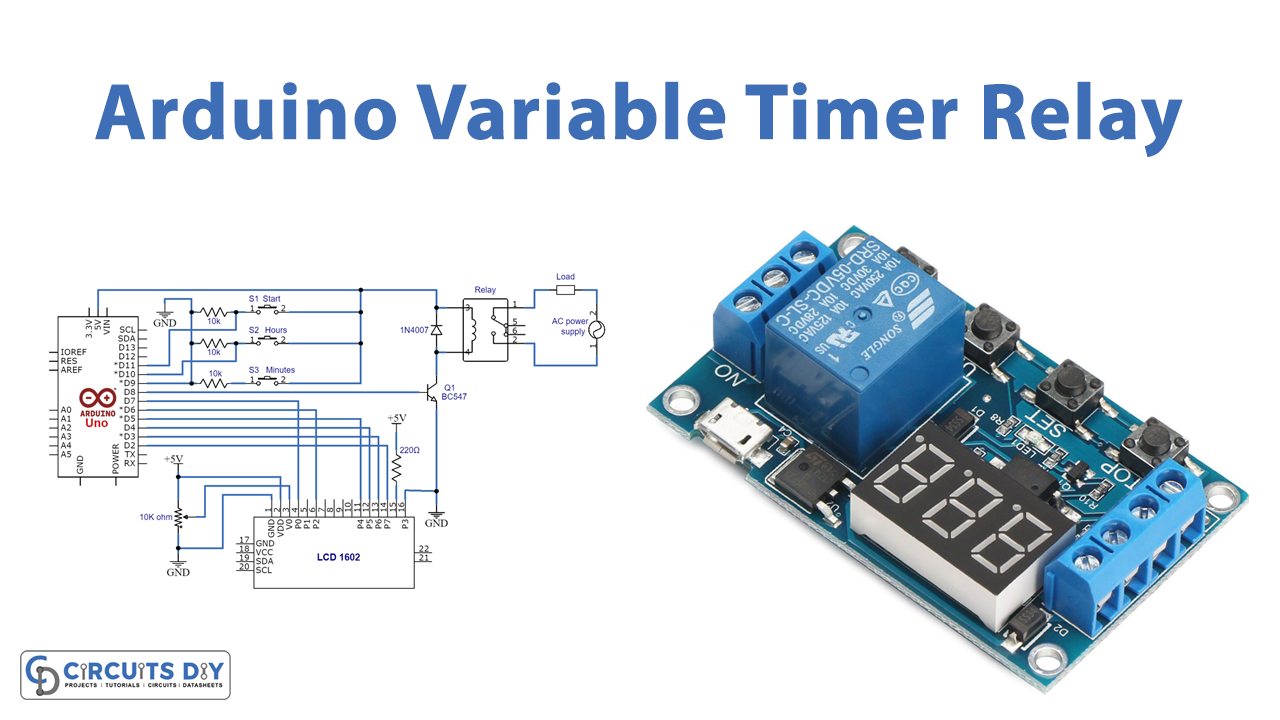
In this tutorial, we are going to make an ” Arduino Variable Timer Relay “. A quick, reliable solution based on Arduino is provided to automate electrical equipment depending on the situation. This Arduino variable timer relay allows us to control high-voltage electronic equipment or devices.
The majority of people who work with electricity are familiar with time relays. It is a well-known and widely used device in the energy sector. Time relay has a reputation for having reliable designs with long service and few maintenance requirements. Timer relays’ practical functioning mechanism allows you to select from a variety of functions and time delay ranges to get the ideal timer for your needs.
What is a timer Relay?
A timer relay is a device that after its coil is activated, periodically changes the condition of its connections. The cycle duration, which can range from a few milliseconds to several hundred hours, is often externally changeable and determines how long the contacts can stay closed or open. The timer’s design will determine how many regulated contacts there are and how long the cycle lasts.
Hardware Required
| S.no | Component | Value | Qty |
|---|---|---|---|
| 1. | Arduino | UNO | 1 |
| 2. | USB Cable Type A to B | – | 1 |
| 3. | Relay | – | 1 |
| 4. | Potentiometer | 10K, 220 Ohm | 3,1 |
| 5. | Diode | 1N4007 | 1 |
| 6. | Switch | 3 | |
| 7. | Resistor | 10K | 3 |
| 8. | LED | 1602 | 1 |
| 9. | BC547 | – | 1 |
| 10. | Jumper Wires | – | – |
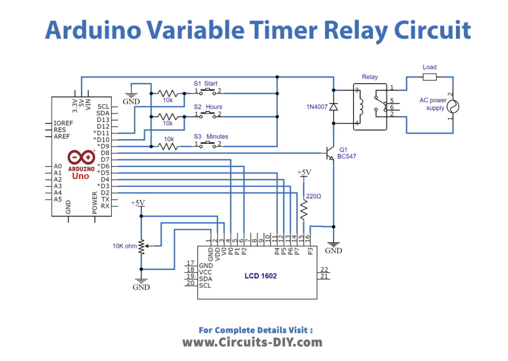
Circuit Diagram
Connection Table
| Arduino | Rotary Encoder |
|---|---|
| GND | GND |
| 5V | Vcc |
| D1 | DT |
| D2 | CLK |
Arduino Code
 #include <LiquidCrystal.h>
LiquidCrystal lcd(7,6,5,4,3,2);
const int set = 9;
int hours=10;
int start=11;
int relay=8;
int b=0,h=0,t=0;
int buttonState = 0;
int lastButtonState = 0;

void setup() {

  pinMode(set,INPUT);
  pinMode(hours,INPUT);
  pinMode(relay,OUTPUT);
  pinMode(start,INPUT);
  lcd.begin(16,2);
  lcd.setCursor(0,0);
  lcd.print("Adjustable Timer");
}
int timer( int b,int h)
{
         if(b<=9)
           {
            lcd.setCursor(3,1);
            lcd.print(0);
            lcd.setCursor(4,1);
            lcd.print(b);
          }
     else{lcd.setCursor(3,1);lcd.print(b);}
         lcd.setCursor(2,1);
         lcd.print(":");
     if(h<=9)
           {
            lcd.setCursor(0,1);
            lcd.print(0);
            lcd.setCursor(1,1);
            lcd.print(h);
          }
     else{lcd.setCursor(0,1);lcd.print(h);}

  }
void loop()
      {

         buttonState = digitalRead(set);

       if (buttonState != lastButtonState)
       {

       if(buttonState == HIGH)
         {

           lcd.clear();
           lcd.print("Set time in min:");

          ++b;
           timer(b,h);

       }

         lastButtonState = buttonState;
          }

      if (digitalRead(hours)== HIGH)

         {
              lcd.clear();
              lcd.print("Set time in hours");
              ++h;
              timer(b,h);
              while(digitalRead(hours)==HIGH);


          }

          if(digitalRead(start)==HIGH)
          {
             lcd.clear();
             t=((h*60)+(b))*1000;
             lcd.print("Timer is set for");
             timer(b,h);
             digitalWrite(relay,HIGH);
             delay(t);
             digitalWrite(relay,LOW);
             while(digitalRead(start) == HIGH );

           }


      }
Lets Test!
It’s now time to test the circuit. Once the circuit gets the power after uploading of code, it will work as soon as you press the switch buttons. Be very careful if you are using the high voltage at the relay end.
Working Explanation
In this project, the SPDT Relay is controlled by an Arduino Uno board, and a 16 x 2 character LCD with the status of the time length. The LCD is wired using digital pins D2 through D7. The VR1 potentiometer aids in controlling the LCD’s contrast, while the BC547 transistor functions as a switching device and regulates the power supply to the relay coil based on the output of the Arduino. If you read the code you will easily understand the work.
Three push buttons are located to establish various time durations: S1 Switch starts the count, S2 modifies the hours, and S3 modifies the minutes. The D8 pin on the Arduino is used to extract the output signal, which then uses a transistor to operate the relay.
Application and Uses
- Star-delta motor starting
- Industrial automation
- Lighting control
- Automatic doors
- Pump controls
- Irrigation systems
- HVAC applications and much more