
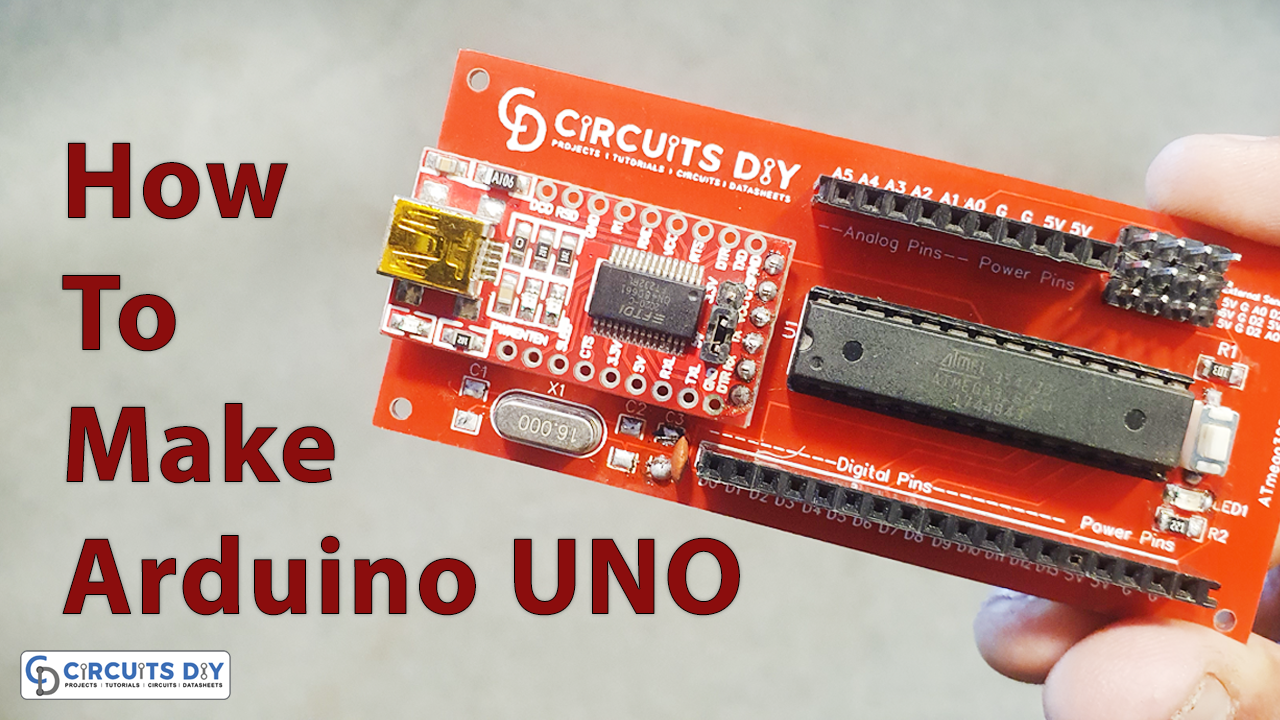
The Arduino uses the ATMega328p chip. We can get that in an SMD format (ATMega328p-AU) or the DIP format for trough hole soldering (ATMega328p-PU). But, the chip by itself can’t work. It needs a few more components and altogether is called the bare minimum configuration of this chip. So In this tutorial, we are going to design our own custom-made “Arduino UNO PCB” using an ATMega328p chip.
PCBWay commits to meeting the needs of its customers from different industries in terms of quality, delivery, cost-effectiveness, and any other demanding requests. As one of the most experienced PCB manufacturers in China. They pride themselves to be your best business partners as well as good friends in every aspect of your PCB needs.
Hardware Table
You will require the following components to make your own Arduino UNO.
| Value | Component | Value | Qty |
|---|---|---|---|
| 1. | IC | ATMega328p | 1 |
| 2. | FTDI Module | R232 | 1 |
| 3. | Crystal Oscillator | 16MHz | 1 |
| 4. | Capacitor | 100nF,22pf | 1 |
| 5. | Resistor | 10k,220 | 1 |
| 6. | Pin Header | – | – |
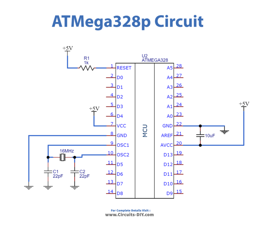
Step 1 – The Simple ATMega328p Circuit
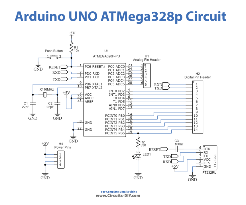
Below we have the schematic for this configuration. As you can see we need a supply of 5 volts. This supply has to be very well regulated with no voltage spikes. For that and an extra 10uF capacitor between 5V and GND. Also, the reset pin is negatively enabled. So, in order to have it disabled, we need to apply 5V to it. For that, a 10k ohms resistor is placed between RESET and Vcc.
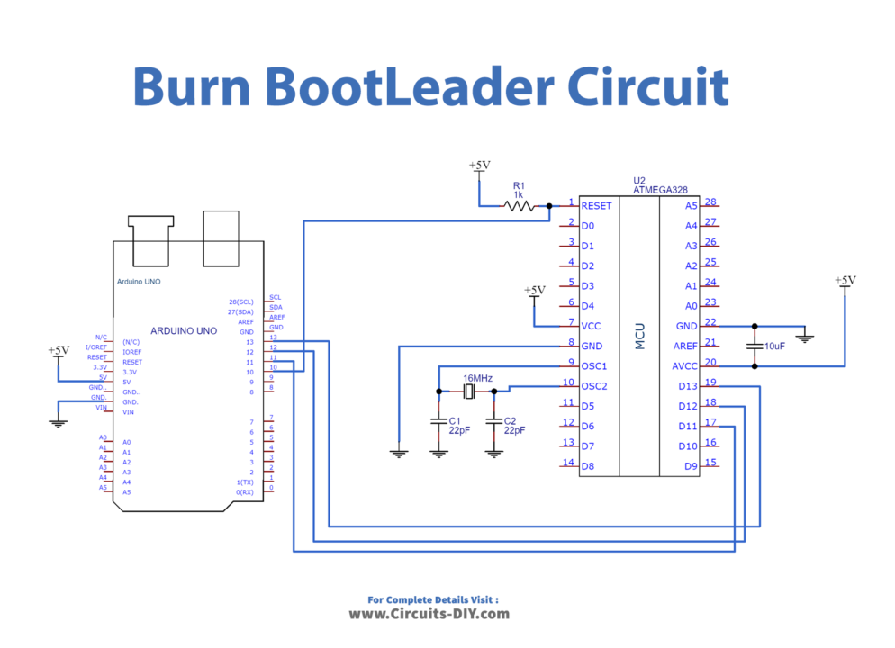
Step 2 – Burn Bootloader
Now, let’s imagine the chip doesn’t have the bootloader (virgin chip). For that, you have to make the next connections from an Arduino UNO. These are the SPI pins, CLOCK, MISO, and MOSI.
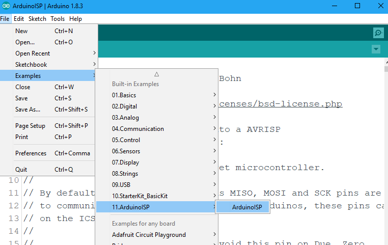
Now connect the Arduino to your PC. Open Arduino IDE and go to File → Examples → Arduino ISP and open that example. Select the com of the Arduino UNO board, select the boar as Arduino UNO and upload this code.
Now make the connections in the past schematic and is time to burn the bootloader. Go to Tools → programmer → Arduino as ISP. By that, we change the programmer to ISP.
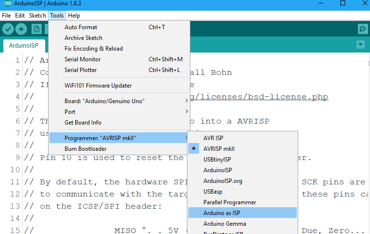
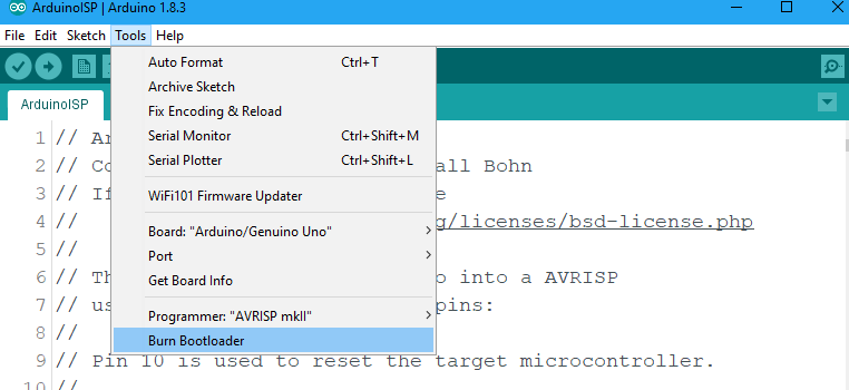
Finally, go to Tools → Burn bootloader. Now the LEDs of the Arduino will blink a lot. Once you get the message of bootloader burned we are good to go.
Step 3 – Upload a Test code
Before Uploading a test code you first need to Install FTDI Module Drivers. Download FTDI 232 Driver and Install It according to your operating system.
Now, we have the bootloader so we can communicate with the RX and TX pins and upload a code. For that, we need an FTDI module. Make the next connections and Upload this code to our designed Arduino board. If LED is blinking so it means you have successfully designed your own custom Arduino board.
Test Code
void setup() {
  // initialize digital pin LED_BUILTIN as an output.
  pinMode(LED_BUILTIN, OUTPUT);
}


void loop() {
  digitalWrite(LED_BUILTIN, HIGH);   // turn the LED on (HIGH is the voltage level)
  delay(1000);                       // wait for a second
  digitalWrite(LED_BUILTIN, LOW);    // turn the LED off by making the voltage LOW
  delay(1000);                       // wait for a second
}
Related posts:
 PCB Manufacturing Process - A Complete Guide For Beginners
 Interfacing 1.8 Inch SPI TFT Color Display Module with Arduino
 Display the LED Brightness on an LCD 16×2 with Arduino UNO
 Button Count on LCD - Arduino Tutorial
 Weighing Scale using Arduino UNO & HX711 Sensor
 Bidirectional Counter using Arduino and IR Sensor


