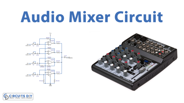
Introduction
While listening to the music, you hear a lot of instruments, sometimes played together at a time. If we play all the musical instruments together, it can make chaos in our ears. But it doesn’t happen when we listen to our favorite music. Why? Because professional music composers utilize audio mixer circuits in their music. So, in this tutorial, we will make an “Audio Mixer Circuit”.
If you use a microphone frequently, you’re probably aware that there are two types of microphones. An audio interface, and an audio mixer. Audio interfaces are devices that link microphones to computers. As a result, it’s only used for one audio recording. A mixing circuit, on the other hand, we employ when there are many instruments or microphones.
Hardware Components
The following components are required to make Audio Mixer Circuit
| S.no | Component | Value | Qty |
|---|---|---|---|
| 1. | IC | LM3900 | 4 |
| 2. | Potentiometer | 1KΩ | 4 |
| 3. | Capacitor | 0.1uF | 5 |
| 4. | Resistor | 1MΩ, 330Ω, 470Ω | 4,2,2 |
| 5. | Battery | 3v | 1 |
| 6. | Connector | 2-Pin | 2 |
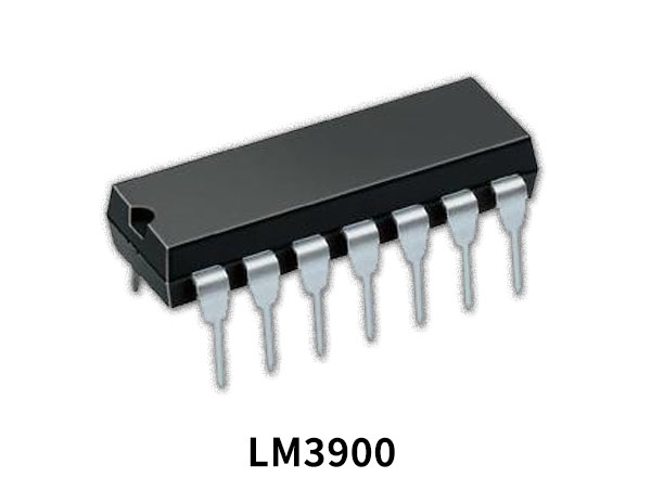
LM3900 Pinout
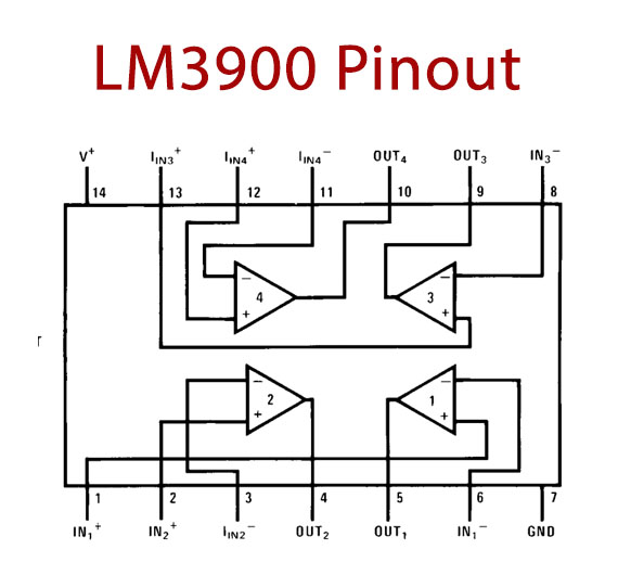
For a detailed description of pinout, dimension features, and specifications download the datasheet of LM3900
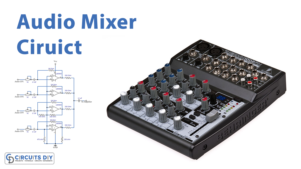
Audio Mixer Circuit
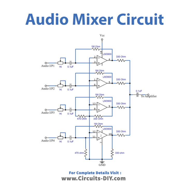
Working Explanation
We require an amplifier stage to construct this Audio Mixer Circuit, and the LM3900 IC is employed here as the amplifier stage. To amplify the audio input signals, all internal amplifiers are used. Each audio input is controlled by variable resistors, allowing us to easily regulate separate audio channels. The audio signals are sent into the amplifier’s inverting input, while the non-inverting pins are grounded. A 1M resistor is there for feedback. Finally, the output signals are merged for use as a power amplifier external to the system.
Application and Uses
- In recording studios and concerts.
- To integrate different sound signals.
- To generate a piece of music by combining sound records from individual instruments such as a microphone, piano, drums, and guitar.