The tone control is a type of equalization used to make specific pitches or “frequencies” in an audio signal softer or louder. A tone control circuit is an electronic circuit that consists of a network of filters that modify the signal before it is fed to speakers, headphones, or recording devices by way of an amplifier. It allows listeners to adjust the sound to their liking and compensate for recording deficiencies, hearing impairments, room acoustics, or shortcomings with playback equipment.
For example, older people with hearing problems may want to increase the loudness of high pitch sounds they have difficulty hearing. It can be used to adjust an audio signal during recording. For instance, if the acoustics of the recording site causes it to absorb some frequencies more than others, tone control can be used to amplify or “boost” the frequencies the room dampens. Here we design a tone control circuit based on two transistors and other easy-to-use components.
Hardware Required
| S.no | Component | Value | Qty |
|---|---|---|---|
| 1. | Operational Amplifier IC | LM741 | |
| 2. | Resistor | 100KΩ,10KΩ,4.7KΩ,1KΩ | 3,1,1,1 |
| 3. | Variable Resistor | 100KΩ | 2 |
| 4. | Capacitor | 10uF,47uF,2.2nF,22nF,220nF | 1,1,1,2,1 |
| 5. | Connecting Wires | – | – |
Circuit Diagram
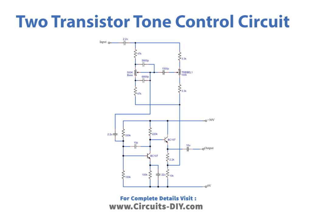
Working Explanation
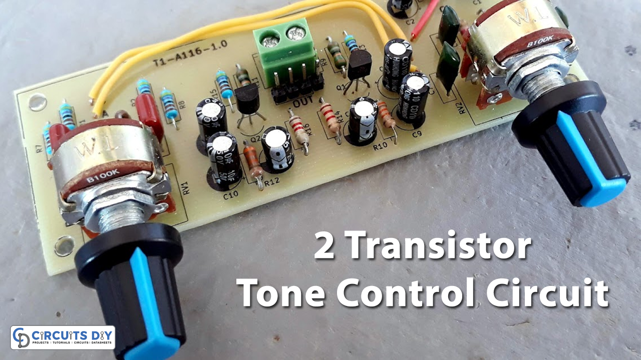
As we can see in the circuit, two NPN transistors (BC107) are used. Here audio input is taken through the 2.2μf capacitor and separated into two lines to control bass and treble effects. Then the output from the tone control elements is fed into a pre-amplifier transistor. Now, this output is synchronized and then fed into the output pins. Now the output is taken from the emitter terminal of the second transistor. And we have used a 30-volt DC power supply to bias this circuit.
Applications
Tone controls are found on many sound systems: radios, portable music players, boomboxes, public address systems, and musical instrument amplifiers.