
The fluorescent lamp driver circuit, as its name suggests, lights up an 8W fluorescent lamp using a circuit involving IC NE555. Since the circuit is portable, therefore, a fluorescent lamp operates on the go.
Hardware Required
| S.no | Component | Value | Qty |
|---|---|---|---|
| 1. | IC | NE555 Timer | 1 |
| 2. | Transformer | 6V, 5-10W | 1 |
| 3. | Fluorescent Lamp | 6W | 1 |
| 4. | Transistor | TIP42 | 1 |
| 5. | Diode | 1N4001 | 1 |
| 6. | Variable resistor | 12KΩ | 1 |
| 7. | Resistors | 330Ω, 510Ω | 1,1 |
| 8. | Capacitor | 0.1µF, 4700pF | 1 |
| 9. | Battery | 6V | 1 |
Circuit Diagram
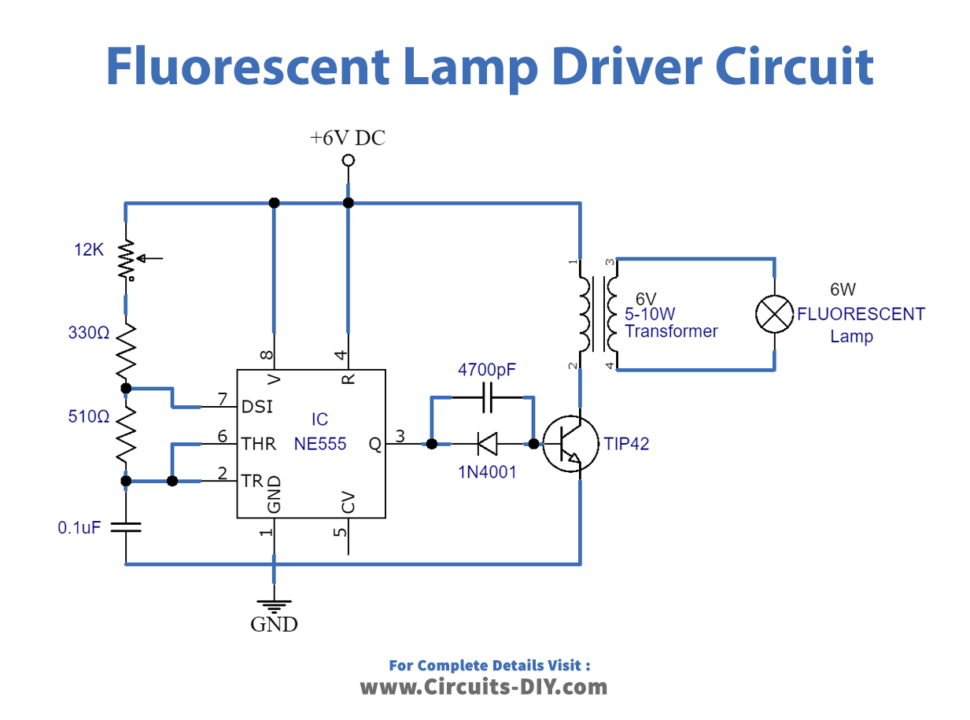
Working Explanation
Here in the circuit, IC NE555 is working in its Astable form of multivibrator mode. The Astable Multivibrator mode of the IC refers to the self-triggering mode where oscillations are created at a particular frequency in the rectangular waveform. The signal generated by NE555 is passed through the diode 1N4001 in order to prevent current reversal. Also, a capacitor at PINOUT 3 of NE555 restores the weak output signal from the IC.
This signal then reaches the PNP power transistor TIP42 which amplifies it. The circuit is such that the transistor gets heated up due to the driving of the lamp, therefore, the heatsink is also attached to the transistor. The amplified signal is still not enough to light a 6W Fluorescent Lamp, hence, a 5W to 10W transformer steps up the voltage. Moreover, the transformer ratings should be 6/230 V. 10KΩ variable resistor adjusts the brightness of the lamp.
Application
- Camping lights
- Transport lightning i.e cars, boats, buses
- Emergency lighting