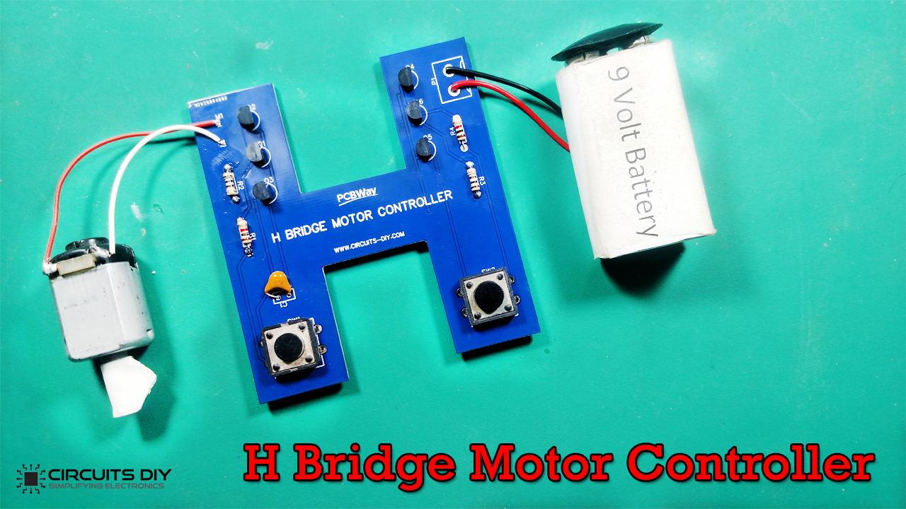
Motor control is the core of automation & robotics. Without locomotion or any movement, a robot is dull and lifeless. The H-bridge Motor Controller is a true concept for DC motor control. It gives you rotary control of the motor: move motors forward, backward, and with varying speeds. In this project, we are going to design an H-Bridge Motor Controller/Driver Circuit for a small 9V DC motor.
In general, an H-bridge is a rather simple circuit, containing at least four switching elements, with the load at the center, in an H-like configuration. The switching elements are usually bi-polar or FET transistors and some high-voltage applications use IGBTs, Integrated solutions also exist but whether the switching elements integrate with their control circuits or not is irrelevant for the most part for this discussion. Usually, diodes are also used to protect the load & switching elements against the sudden change in polarities.
One of the bridges is connected to a power supply (battery for example) and the other end is grounded. Though the load can be anything you want, by far the most useful application of an H-bridge circuit is with a brushed DC or stepper motor load.
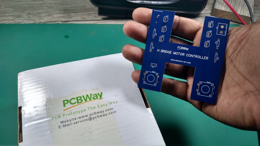
PCBWay commits to meeting the needs of its customers from different industries in terms of quality, delivery, cost-effectiveness, and any other demanding requests. As one of the most experienced PCB manufacturers in China. They pride themselves to be your best business partners as well as good friends in every aspect of your PCB needs.
Hardware Components
The following components are required to make H-Bridge Motor Driver Circuit
| S. no | Component | Value | Qty |
|---|---|---|---|
| 1. | DC Motor | – | 1 |
| 2. | Transistor | BC547, BC557 | 2, 4 |
| 3. | H-Bridge PCB | – | 4 |
| 4. | Ceramic Capacitor | 100nf | 1 |
| 5. | Resistors | 100, 1K | 2, 2 |
| 6. | Battery | 9V | 1 |
BC547 Pinout

For a detailed description of pinout, dimension features, and specifications download the datasheet of BC547
BC557 Pinout
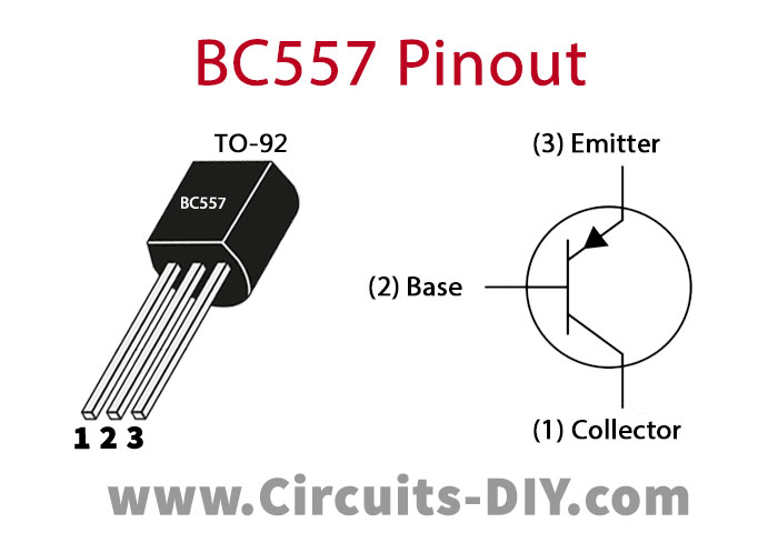
For a detailed description of pinout, dimension features, and specifications download the datasheet of BC557
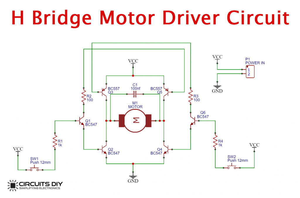
H-Bridge Motor Driver Circuit
Steps
Follow All Steps Carefully from the Video Tutorial Above (Recommended)
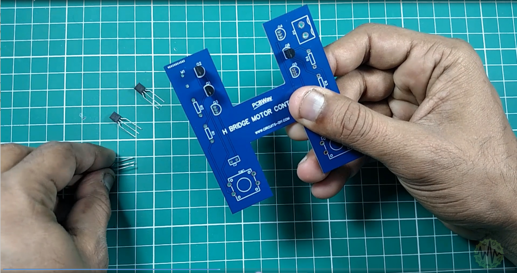
1) Solder All Transistors
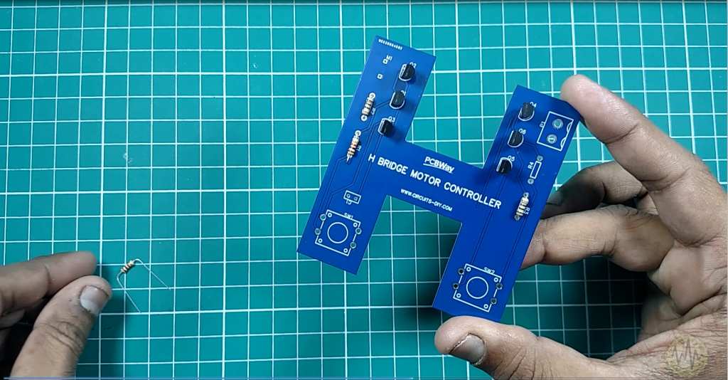
2) Solder All Resistors
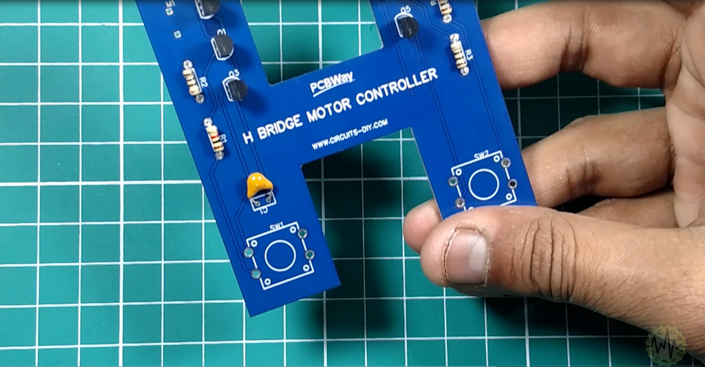
3) Solder Ceramic Capacitor
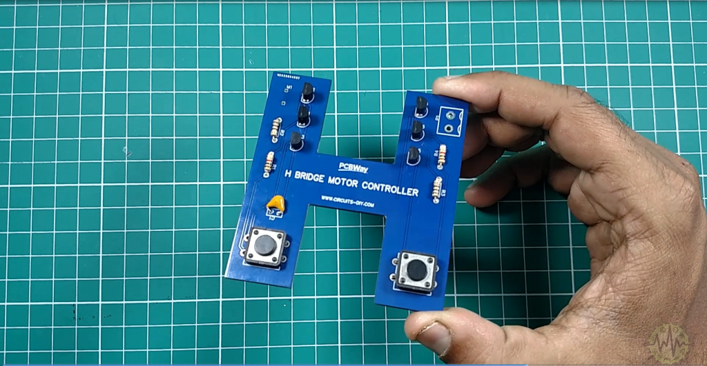
4) Solder Push Buttons
5) Solder Power Connector
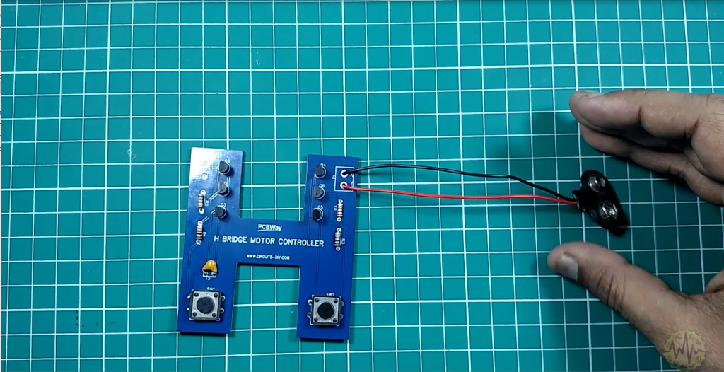
6) Solder DC Motor Input Wires
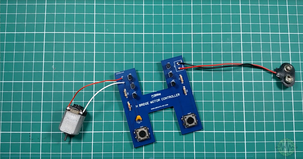
7) Let’s Power up the Circuit
Working Explanation
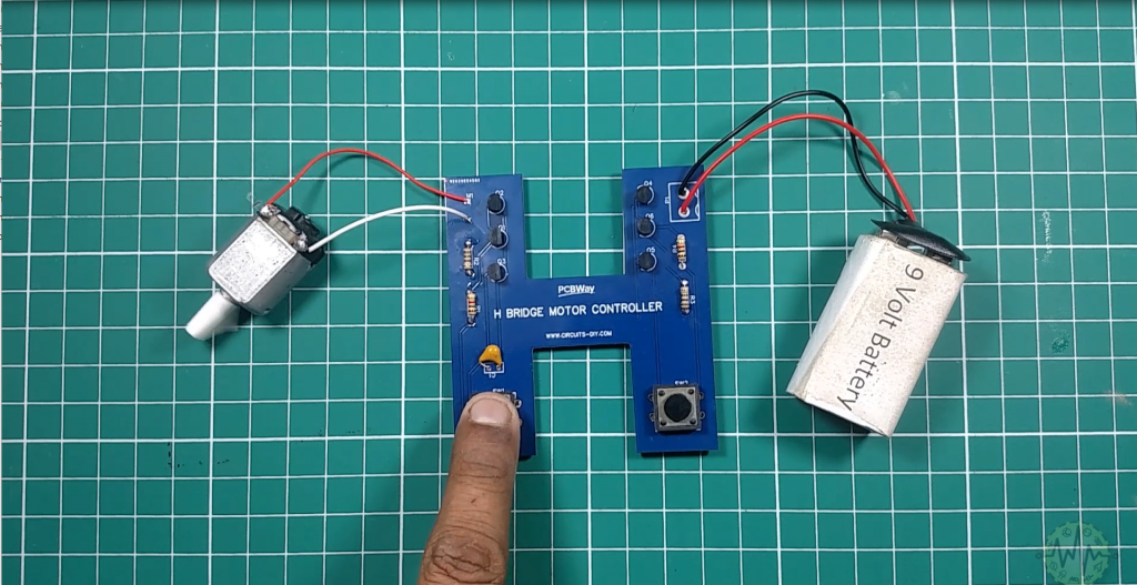
The circuit shown below is a modified H-Bridge DC Motor controller. Resistors R1 to R4 limit the base current of their corresponding transistors. On completing the circuit & pressing the pushbutton SW1, transistors Q3 and Q4 will be on and the current passes through the motor from left to right and the motor starts its rotation in the respective direction.
On pressing the pushbutton SW2, transistors Q5 and Q2 will be on and current passes through the motor from right to right making the motor to rotate in the opposite direction. You should never press both switches at the same time. If you do that, you will create a very low-resistance path between the Power and GND, effectively short-circuiting your power supply. This condition is called ‘shoot-through’ and is a sure-fire way to quickly destroy your H-bridge.
Applications
- Commonly used in robotic applications to control DC motors of devices such as robotic arms.
Related posts:
 Sensitive Clap Switch Circuit Using CD4017 Decade Counter
 Mobile Phone Detector Circuit - Electronics Projects
 Brake Failure Indicator Circuit using 555 Timer - Electronics Project
 High Voltage Transformer Using 18650 Li-ion Battery & IRF3205 MOSFET
 How to Make Clap Switch | DIY Project | Home Automation | Electronics Projects
 How to Make a Simple Fire Alarm Circuit using LM358 IC - Electronics Projects