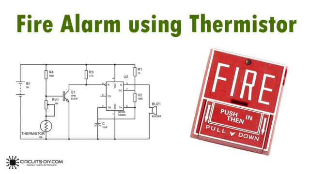
Introduction
A fire alarm circuit is an important safety device that can detect the presence of smoke or heat and trigger an alarm in the event of a fire. This article will show you how to build a high-temperature fire alarm circuit using transistors. This circuit is designed to detect high temperatures and trigger an alarm before a fire even starts, providing an early warning and giving you time to take action.
The circuit is simple to build and can be a fun and educational project for anyone interested in electronics and safety technology.
Components Required
You will require the following hardware for High-Temperature Fire Alarm Circuit.
| S.no | Components | Value | QTY |
|---|---|---|---|
| 1 | IC | UM3561 | 1 |
| 2 | Transistor | 2N2907, 2N2222, BC547 | 1, 1, 1 |
| 3 | Resistor | 10K, 220K, 470E, 56E | 1, 1, 1, 1 |
| 4 | Relay | 9V | 1 |
| 5 | Zener | 3V | 1 |
| 6 | Diode | 1N4148 | 1 |
| 7 | Speaker | 8OHM | 1 |
| 8 | LED | – | 1 |
Steps to Make High-Temperature Fire Alarm Circuit

Connections
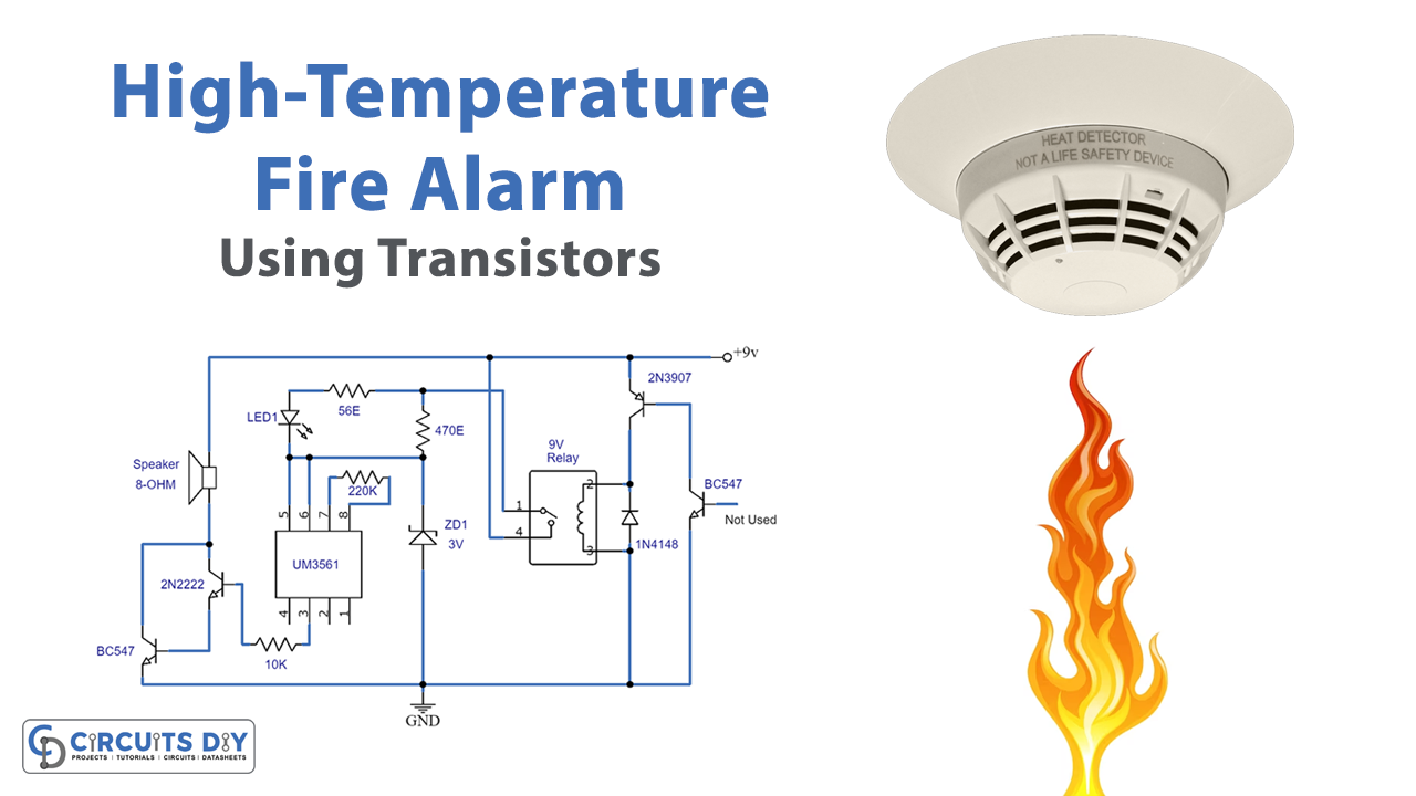
- Connect the collector of NPN transistor Q1 (BC109) to the base of PNP Germanium transistor Q2 (AC188)
- Connect the collector of Q2 to the RY1 relay
- Connect Pin 5 and 6 of the IC UM3561 to a 3v power supply unit
- Connect Pin 2 of the IC to the ground
- Connect the R2 resistor between Pin 7 and Pin 8 of the IC to limit the oscillator frequency
- Connect the collector of Q3 to the base of Q4 to form a Darlington Compound
- Connect R4 between the Darlington Compound and the Zener Diode series to control the voltage supply on IC1
- Connect R1 in series with LED1 and parallel with R4
Working Explanation
This circuit is a simple fire alarm that combines a silicon NPN transistor (Q1) and a PNP Germanium transistor (Q2) to detect heat. Q1 is connected to Q2, which is then connected to a relay (RY1). The IC-UM3561 is also used in this circuit, which generates a siren sound when connected to a 3v power supply.
The IC’s pins 5 and 6 are connected to the power supply, and pin 2 is connected to the ground. The R2 resistor is used to limit the oscillator frequency, and the R4 resistor is used to boost the signal from the IC1. The output is then sent to Q3 and Q4 transistors using the Darlington Compound process. The circuit also includes a Zener Diode series to control the voltage supply on IC1, and an LED1 and R1 resistor in series, which is connected in parallel to R4. The circuit automatically generates an alarm when the system detects a temperature that exceeds the permissible limit.
Final Words
the high-temperature fire alarm circuit using transistors is a great way to detect high temperatures and trigger an alarm when a fire happens. You can use it for home, office, or industrial applications, where early warning can save lives and prevent damage. Happy building!