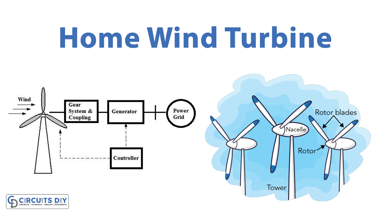
In this tutorial, we are going to make a “Home Wind Turbine Circuit”. Small wind turbines are a great way to reduce your reliance on the grid. They’re becoming more popular, as people become aware of their benefits. We always trying to get unlimited electrical energy without spending money. If you seek to save money or play a part in solving the world’s energy crisis, a wind turbine for your home is an excellent idea. Small wind turbines work by converting the wind’s kinetic energy into electrical current.
The blades on the turbine catch the wind, and the rotor spins. This spin turns a generator, which produces electricity that you can use to power your home. Here is the simple design proposed, such as a small wind turbine for home use or low-power usage. It requires a low initial cost and gives the best return, in terms of electrical energy.
Design of Windmill generator
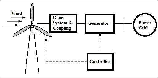
Here this small 12V wind turbine generator is capable of producing alternate energy through the wind. In the first stage, the bridge rectifier and controller rectify the energy, that came from the wind turbine generator. And then the regulator-battery charger circuit helps the 12V/4.5Ah SLA battery, to get charging. At the final stage, the step-up inverter circuit produces a high-voltage enough AC. Which is used to operate home appliances.
Circuit Diagram
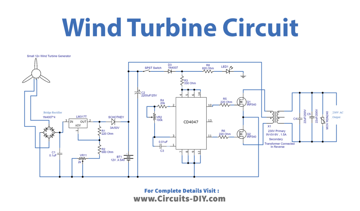
Construction and Working
This small wind turbine circuit has five stages which are given below,
- 12V Wind turbine generator/Bridge Rectifier Circuit
- Regulator / Battery charger circuit
- Inverter circuit using IC CD4047
- Mosfet Drivers
- Output Stage
12V Wind Turbine Generator/ Bridge Rectifier
In this stage, a 12 Volt wind turbine or windmill is available with different watts range. You can choose according to your requirement. And bridge rectifier converts the AC supply into DC, and here we used a 1N4007 diode as a bridge rectifier element. Which converts the energy from a wind turbine into Direct Current (DC) supply.
Regulator / Battery Charger
Here in this stage, the LM317 adjustable three-terminal positive voltage regulator is used. This voltage regulator can give an output voltage range from 1.25 V to 37 V, with more than a 1.5A current rating. The final output from the regulator is given to the 12/4.5Ah SLA Battery, this Battery provides DC bias to the inverter circuit. We can calculate the output voltage Vout of regulator LM317 from the given mathematical expression.
Vout = 1.25V(R2/(R1+1))
R2 => R2+VR1 for the given inverter circuit.
Inverter Circuit using IC CD4047 (Switching Pulse Oscillator)
In this stage, to produce a switching pulse we have used a monostable/astable multivibrator IC CD4047. This IC works in low power and is available in 14 pins dual in-line package. It provides full oscillation output F at Pin 13, 1/2 of oscillation at Pin 10 as Q, and Pin 11 as Q’. And each output pin gives a 50% duty cycle.
f = (1/8.8RC)
Here R => R4+VR2 and C=> C3. By using this formula, we can obtain frequency output at pin 13. For pins 10 and 11. The formula changes as f=1/4.4RC.
MOSFET drivers
Here we need switching drivers for this inverter circuit, therefore we have used IRF540 N channel power Mosfet from Vishay silicon mix. It gives fast switching and has high operating temperature characteristics (175ºC).
Output Stage
This stage is the main part of the wind turbine generator, here transformer X1 is used in reverse with specifications as 230V primary, 9V-0-9V / 1.5A secondary winding center tapped transformer. MOV (Metal Oxide Varistor) protects electronic devices connected to the output.
Now wind turbine generator output voltage is directly fed into the LM317 positive regulator circuit, and it is adjusted to give 12-volt output. Here battery is connected to this bias through a (3A, 50V) Schottky diode. This circuit Involves high voltage, so handle it with extreme care.
Working Explanation
As we know that the CD4047 IC is connected and configured as an astable multivibrator. When we turn ON the SPST switch, this circuit starts oscillating. Output Q and Q’ are directly fed into switching power MOSFET IRF540 & drive X1 transformer secondary winding. Then the current flow occurs for a particular duration. So varying electromagnet induced, and primary winding coil produces EMF. By which we get alternating current output. Now voltage/frequency gets varied, depending on the count of winding and switching frequency output.
Applications
We can use this small wind turbine circuit and set it up to charge the laptop, to charge electronic gadgets or electronic appliances in homes and outstations.