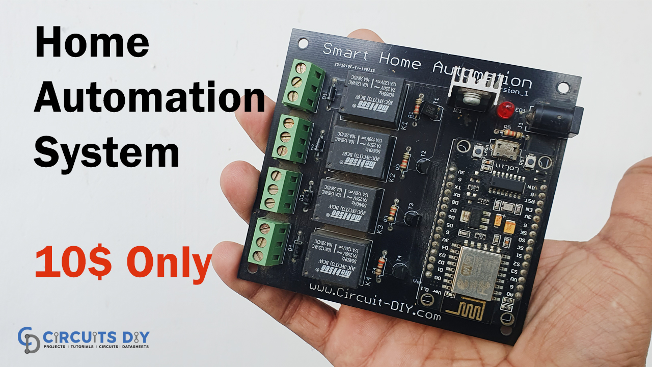
Introduction
As technology is rising, we are smart ways for everything. Smart automation is one of those smart ways, that provides home automation in a more comfortable way. Imagine it’s cold in and you just come in your blanket on your bed but you realized you forget to turn OFF your washroom’s light? Now you want to turn OFF those lights without having to leave your bed.
This is where the smart automation system comes in. It may seem difficult but It’s actually a lot easier than it appears to set up your home automation system. To make things easier we are here with the tutorial on Smart Home Automation Control System.
PCBWay commits to meeting the needs of its customers from different industries in terms of quality, delivery, cost-effectiveness, and any other demanding requests. As one of the most experienced PCB manufacturers in China. They pride themselves to be your best business partners as well as good friends in every aspect of your PCB needs.
Hardware Components
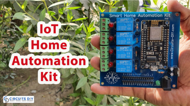
The following components are required to make Home Automation Control System Circuit
| S.no | Components | Value | Qty |
|---|---|---|---|
| 1. | PCB board for circuit | – | 1 |
| 2. | Node MCU | ESP8266 | 1 |
| 3. | Relay | 5V | 4 |
| 4. | Diodes | 1N4007 | 4 |
| 5. | Resistor | 330 ohms | 5 |
| 6. | Transistor | BC547 | 4 |
| 7. | Terminal block | 5mm | 1 |
| 8. | Voltage Regulator IC | LM7805 | 1 |
| 9. | Power LED | – | 1 |
| 10. | DC Power Jack | – | 1 |
| 11. | Power Supply | 12V | 1 |
ESP8266 Pinout
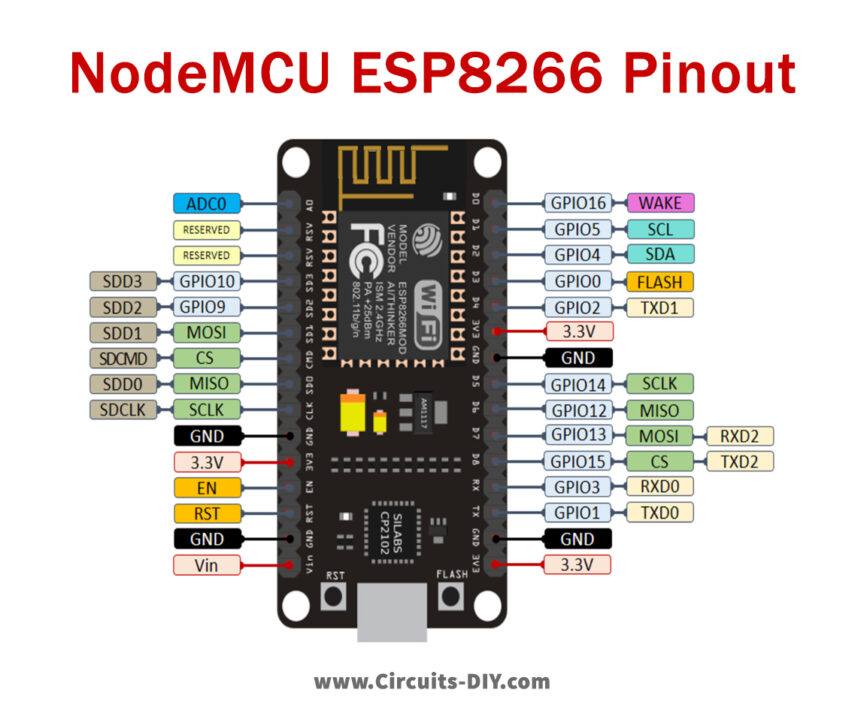
For a detailed description of pinout, dimension features, and specifications download the datasheet of ESP8266
LM7805 Pinout

For a detailed description of pinout, dimension features, and specifications download the datasheet of LM7805
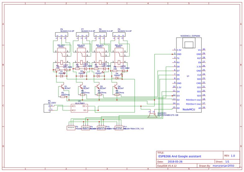
Home Automation Control System Circuit
Code
#include
#include
#define FIREBASE_HOST "basic-2db74.firebaseio.com"                  // Your Firebase Project URL goes here without "http:" , "\" and "/"
#define FIREBASE_AUTH "WljQ8JpTdYqUAnp7VCPgcOshaL90zJtvW83NHAov"    // Your Firebase Database Secret goes here
#define WIFI_SSID "TP-LINK_CD2ED6"                                  // your WiFi SSID for which yout NodeMCU connects
#define WIFI_PASSWORD "20244064"                                    // your WiFi PASSWORD

#define Relay1 12 //D6
int val1;

#define Relay2 14 //D2
int val2;

#define Relay3 4  //D1
int val3;

#define Relay4 5 //D5
int val4;

void setup()
{
  Serial.begin(115200);                                                   // Select the same baud rate if you want to see the datas on Serial Monitor
  pinMode(Relay1,OUTPUT);
  pinMode(Relay2,OUTPUT);
  pinMode(Relay3,OUTPUT);
  pinMode(Relay4,OUTPUT);

  digitalWrite(Relay1,HIGH);
  digitalWrite(Relay2,HIGH);
  digitalWrite(Relay3,HIGH);
  digitalWrite(Relay4,HIGH);

  WiFi.begin(WIFI_SSID,WIFI_PASSWORD);
  Serial.print("connecting");
  while (WiFi.status()!=WL_CONNECTED){
    Serial.print(".");
    delay(500);
  }
  Serial.println();
  Serial.print("connected:");
  Serial.println(WiFi.localIP());

  Firebase.begin(FIREBASE_HOST);
  Firebase.setInt("S1",0);                     //Here the varialbe"S1","S2","S3" and "S4" needs to be the one which is used in our Firebase and MIT App Inventor
  Firebase.setInt("S2",0);
  Firebase.setInt("S3",0);
  Firebase.setInt("S4",0);

}
void firebasereconnect()
{
  Serial.println("Trying to reconnect");
    Firebase.begin(FIREBASE_HOST);
  }

void loop()
{
  if (Firebase.failed())
      {
      Serial.print("setting number failed:");
      Serial.println(Firebase.error());
      firebasereconnect();
      return;
      }

  val1=Firebase.getString("S1").toInt();                                        //Reading the value of the varialble Status from the firebase

  if(val1==1)                                                             // If, the Status is 1, turn on the Relay1
     {
      digitalWrite(Relay1,LOW);
      Serial.println("Relay 1 ON");
    }
    else if(val1==0)                                                      // If, the Status is 0, turn Off the Relay1
    {
      digitalWrite(Relay1,HIGH);
      Serial.println("Relay 1 OFF");
    }

  val2=Firebase.getString("S2").toInt();                                        //Reading the value of the varialble Status from the firebase

  if(val2==1)                                                             // If, the Status is 1, turn on the Relay2
     {
      digitalWrite(Relay2,LOW);
      Serial.println("Relay 2 ON");
    }
    else if(val2==0)                                                      // If, the Status is 0, turn Off the Relay2
    {
      digitalWrite(Relay2,HIGH);
      Serial.println("Relay 2 OFF");
    }

   val3=Firebase.getString("S3").toInt();                                        //Reading the value of the varialble Status from the firebase

  if(val3==1)                                                             // If, the Status is 1, turn on the Relay3
     {
      digitalWrite(Relay3,LOW);
      Serial.println("Relay 3 ON");
    }
    else if(val3==0)                                                      // If, the Status is 0, turn Off the Relay3
    {
      digitalWrite(Relay3,HIGH);
      Serial.println("Relay 3 OFF");
    }

   val4=Firebase.getString("S4").toInt();                                        //Reading the value of the varialble Status from the firebase

  if(val4==1)                                                             // If, the Status is 1, turn on the Relay4
     {
      digitalWrite(Relay4,LOW);
      Serial.println("Relay 4 ON");
    }
    else if(val4==0)                                                      // If, the Status is 0, turn Off the Relay4
    {
      digitalWrite(Relay4,HIGH);
      Serial.println("Relay 4 OFF");
    }
}
Useful steps
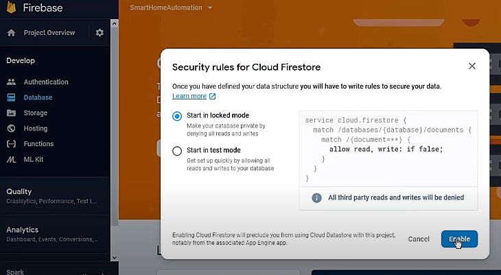
Firebase Setup
Log in to the Firebase Console with your email address at https://console.firebase.google.com/. After logging in successfully, select the “Add Project” option to enter the name of your project. After that, establish a project database and set it to “Locked mode.” Change the option to “Realtime Database” in the upper left corner and let the database produce firebase code. Make a few minor adjustments to the code as shown in the video. Copy and paste the database URL into the Arduino code. Ensure the revised Arduino code doesn’t have “HTTP: and //” in it. Return to the Firebase server now, and Copy the authentication code from Project Settings and paste it into the Arduino code. Update the Arduino’s wifi SSID and password. Update the code and upload it to the hardware setup.
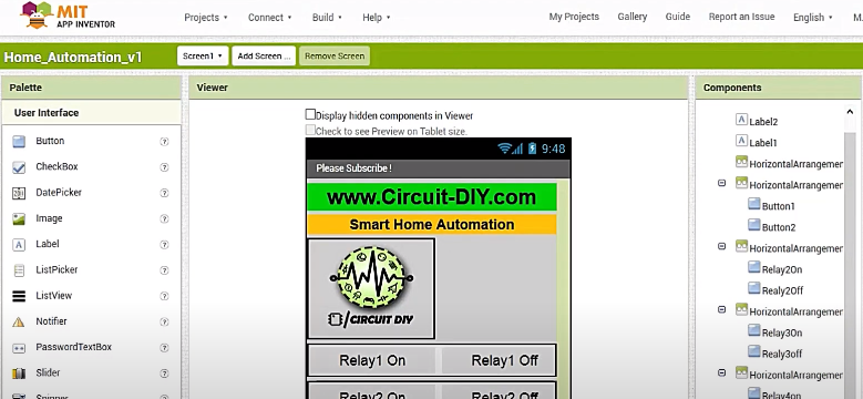
IoT App Setup
In the Google search bar, type “MIT App Inventor 2.” Sign in with your email address and import the “ai” file provided. As stated in the video instructional above, follow the directions. Update the firebase URL and authentication code in their proper places by clicking on the firebase icon. Create the project, and your Smart Home Automation system is now ready to be put to the test.
Code Explanation
- Download the libraries “ArduinoJson” and “Firebase-Arduino-master” files and add them to the Arduino library
- Include and define their necessary parameters. Also, define relays that are connected with Arduino.
- In void setup, define all the relays as output and set them high. Also, include the Wi-Fi begin () to initialize the Wi-Fi library’s network settings and to provide the current status. Also, initialize firebase.
- In a void loop, we gave conditions to turn ON and OFF the relays.
Working Explanation
In this Smart Home Automation Control System, The Node MCU is basically the major component working as a brain, that is controlling device. We transferred the data from the IoT Android App to the cloud-based Firebase real-time database. The Wi-Fi module linked to the Node MCU then receives the transmitted data. As a result, the Node MCU receives and analyses data and deals with the switching of electrical devices attached to the Relay.
Application and Uses
- The circuit is for controlling different devices used in a home.
- One can also utilize the circuit for office automation.
- With some modification, we can employ it for industrial automation devices