Introduction
What do you do when you play any video on your smartphone? You change the direction of the screen and immediately the screen changes from portrait to landscape. Have you wondered how it happens? It’s because of the accelerometer inside your smartphone. So, when you tilt the screen, it automatically changes it to landscape mode. This is the reason that accelerometers are highly utilized in gaming devices, sports applications, tilt sensing applications, etc. Therefore, In this tutorial, we are going to interface “ADXL335 Accelerometer with Arduino UNO”.
How Accelerometer Works?
Certainly, an accelerometer is a device that senses vibrations and accelerations. Since acceleration is defined as the change of velocity in a body or a thing with respect to time. An accelerometer senses these vibrations produced by the body and used this for the adjustment of direction. It senses the acceleration and vibration and transforms them into pressure or stress, essentially the piezoelectric effect. This energy is then get converted into electrical voltage. Now, electrical voltage is employed to get the orientation of any device. In other words, it transforms mechanical energy (basically, vibrations) into electrical energy.
Brief Overview of ADXL335 Accelerometer
ADXL335 is a module that takes the analog input and measures the acceleration in the three dimensions, which are X, Y, and Z. Most importantly, used in the construction machines like drilling machines. Also, in the human sports devices like running, walking, etc. In short, this low-power, low-noise module can easily be interfaced with any microcontroller. Thus, we are using Arduino for this purpose.

Hardware Required
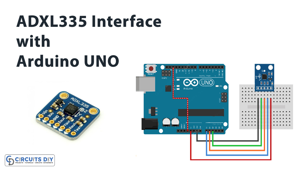
Circuit Diagram
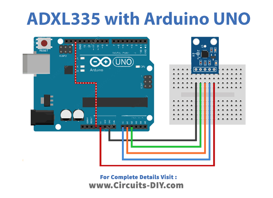
Connection Table
| Arduino | ADXL335 Accelerometer |
|---|---|
| 5V | VCC |
| A0 | X-OUT |
| A1 | Y-OUT |
| A2 | Z-OUT |
| GND | GND |
Arduino Code
Reading ADXL335 accelerometer
const int xInput = A0;
const int yInput = A1;
const int zInput = A2;

// initialize minimum and maximum Raw Ranges for each axis
int RawMin = 0;
int RawMax = 1023;

// Take multiple samples to reduce noise
const int sampleSize = 10;

void setup()
{
	analogReference(EXTERNAL);
	Serial.begin(9600);
}

void loop()
{
	//Read raw values
	int xRaw = ReadAxis(xInput);
	int yRaw = ReadAxis(yInput);
	int zRaw = ReadAxis(zInput);

	// Convert raw values to 'milli-Gs"
	long xScaled = map(xRaw, RawMin, RawMax, -3000, 3000);
	long yScaled = map(yRaw, RawMin, RawMax, -3000, 3000);
	long zScaled = map(zRaw, RawMin, RawMax, -3000, 3000);

	// re-scale to fractional Gs
	float xAccel = xScaled / 1000.0;
	float yAccel = yScaled / 1000.0;
	float zAccel = zScaled / 1000.0;

	Serial.print("X, Y, Z  :: ");
	Serial.print(xRaw);
	Serial.print(", ");
	Serial.print(yRaw);
	Serial.print(", ");
	Serial.print(zRaw);
	Serial.print(" :: ");
	Serial.print(xAccel,0);
	Serial.print("G, ");
	Serial.print(yAccel,0);
	Serial.print("G, ");
	Serial.print(zAccel,0);
	Serial.println("G");

	delay(200);
}

// Take samples and return the average
int ReadAxis(int axisPin)
{
	long reading = 0;
	analogRead(axisPin);
	delay(1);
	for (int i = 0; i < sampleSize; i++)
	{
	reading += analogRead(axisPin);
	}
	return reading/sampleSize;
}
Working Explanation
To interface ADXL335 Accelerometer with Arduino UNO, connect the circuit according to the above-mentioned schematic. Now, copy the above code and paste it into your Arduino IDE. After that, upload this code to the Arduino UNO. Open the serial monitor. Now, you can see the values of the X, y, and Z-axis. To notice the changes in the values, change the direction of the module. As a result, the values would get changed.
Code Explanation
- The coding starts by setting the input Arduino pins that are connected with the sensors’ output pins. After that, we have defined the maximum and minimum values that Arduino is providing. Since Arduino has the 10 bit digital to analog converter, therefore the integer values would be between 0 and 1023. Thus, we set the RawMin as 0 and RawMax as 1023. Moreover, the variable SampleSize is used to take the samples to reduce noise. We have defined the sample size as 10 to take the 10 samples.
- In the void setup, we have set the analogReferance to EXTERNAL. This is for the connection that we have given to the Arduino supply pin with the AREF pin of the module.
- In the void loop, to read the output from the X, Y, and Z-axis, we have called the function readAxis. The readAxis function takes the 10 samples from analog to digital converter of an Arduino and delivers the average value. The map function is the method to map the values. For instance, take this function map (yRaw, RawMin, RawMax, -3000, 3000), this will map the RawMinValue to -3000, RawMax value to 3000 at the y-axis. Now, to scale down the values, the code is formulated using the Scaled function. Finally, the values got printed by using Seiral.print.
Application and Uses
- Firstly, it is used in the wearable devices of sports.
- Further, In smartphones.
- Moreover, for the devices that need safety.
- Also, in the devices that are used to monitor the movements.