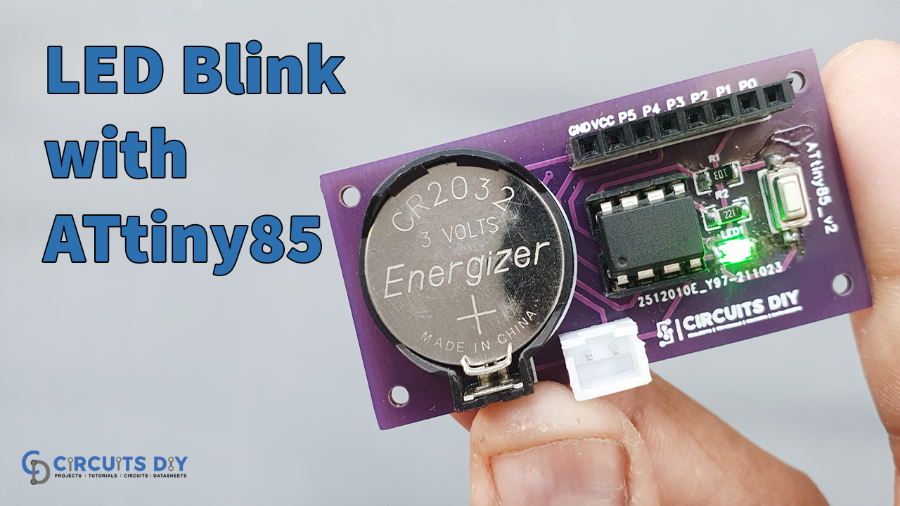
Introduction
Regularly we see Light Emitting diodes (LEDs) are utilized in every other electronic circuit. Particularly, it is utilized regularly at the load side for indication. In-home lighting frameworks, vehicle indicators, signal warnings, game devices, on various occasions for decoration. We utilize LEDs all over. And therefore we have already made a lot of circuit tutorials of LEDs, also we have interfaced them with Arduino. But, how about we attempt to an interface that LED with ATtiny85? So, In this tutorial, we will learn “How to Blink an LED with ATtiny85 Microcontroller”.
It is not very difficult to interface components or sensors with ATtiny85 because it supports Arduino IDE for their programming. Moreover, its programming is pretty much the same as the Arduino controllers. You only require a little bit of prior knowledge of how to burn or upload the code in ATtiny85 IC using Arduino.
This Project is sponsored by PCBWay. They have an open-source community, people can share their design projects with each other. Moreover, every time people place an order for your board, PCBWay will donate 10% of the cost of PCB to you, for your contribution to the Open Source Community.
Hardware Required
| Sr. No | Components | Value | Qty |
|---|---|---|---|
| 1 | SMD Resistor | 220,10k | 1,1 |
| 2 | SMD LED | – | 1 |
| 3 | Socket | CR2032 | 1 |
| 4 | IC | ATtiny85 | 1 |
| 5 | Female Header | – | 1 |
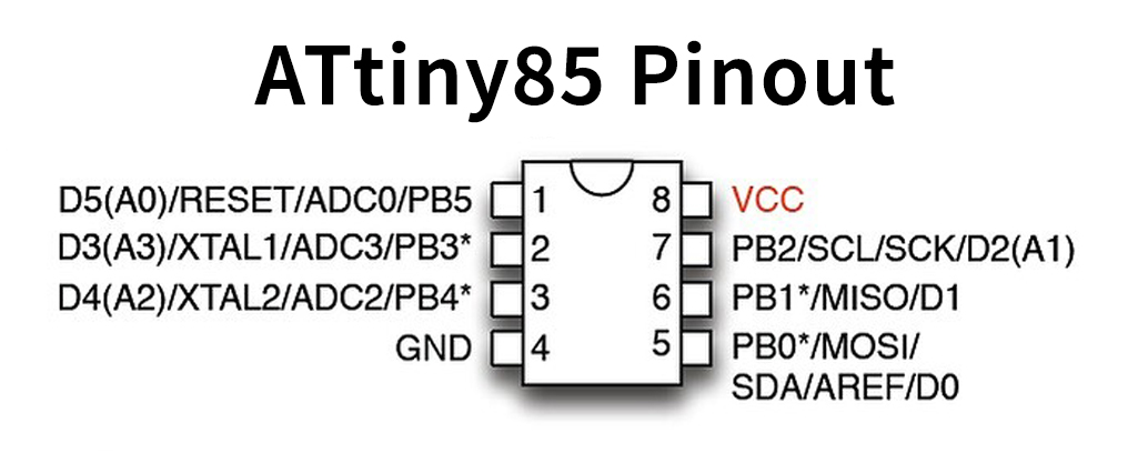
ATtiny85 Pinout
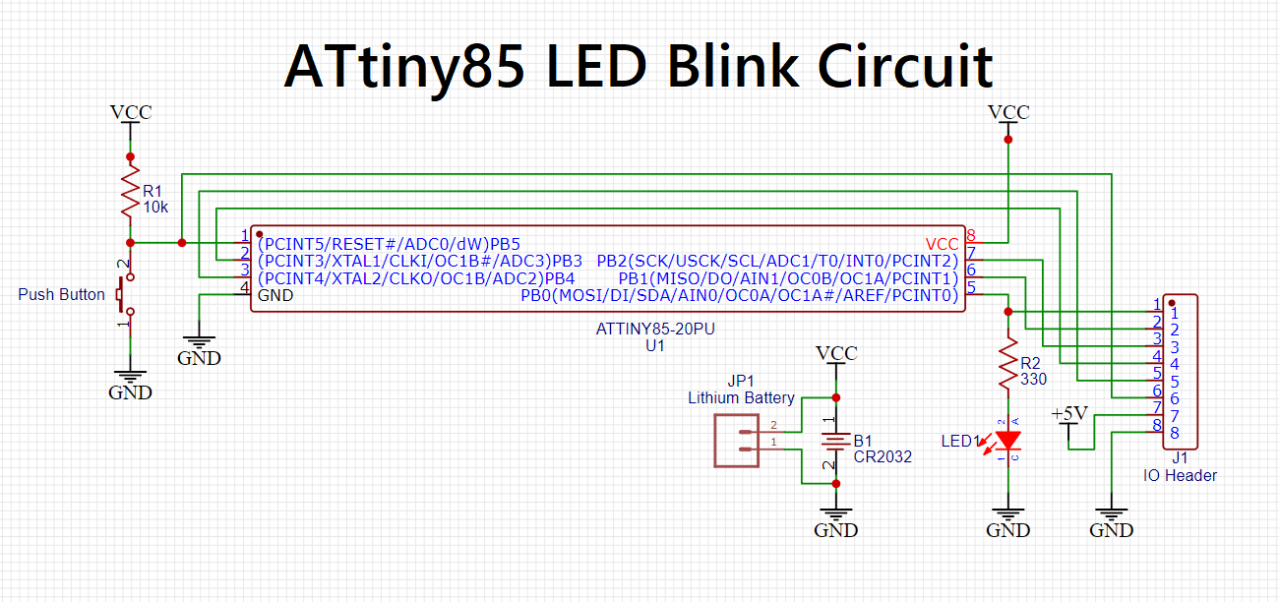
Circuit Diagram
Arduino Code
// the setup function runs once when you press reset or power the board
void setup() {
  // initialize digital pin LED_BUILTIN as an output.
  pinMode(0, OUTPUT);
}

// the loop function runs over and over again forever
void loop() {
  digitalWrite(0, HIGH);   // turn the LED on (HIGH is the voltage level)
  delay(1000);                       // wait for a second
  digitalWrite(0, LOW);    // turn the LED off by making the voltage LOW
  delay(1000);                       // wait for a second
}
Working Explanation
First, you need to connect the circuit according to the above-given diagram. After that write the code on Arduino IDE. Now, use Arduino to burn the code in IC. You can check our article for this purpose. Provide the supply and the LED starts blinking according to the given code.
Code Explanation
- After writing and compiling the code, upload this in your ATtiny85 controller IC
- As you know that in void setup we define our pin modes. So, we did the same. We have defined pin 0 as our output because we connect our output LED to this pin.
- In the void loop function, we have used the command digitalWrite. Basically, this command lowers or higher the pin to no voltage or voltage respectively. So when we write digitalWrite(0, high), it gives voltage to LED, therefore it glows, then we apply little delay. And, after that, we write digitalWrite(0, low), now it provides 0v to pin 0. Hence, the LED turns OFF. Since this is in a void loop, therefore it happens again and again and we observe the blinking of an LED until we turn OFF the supply.
Application
- In portable electronic devices for indication purpose.
- In vehicle indicators.
- Medical applications like operation theatres.
- In offices, to show that person is occupied with work, etc