Introduction
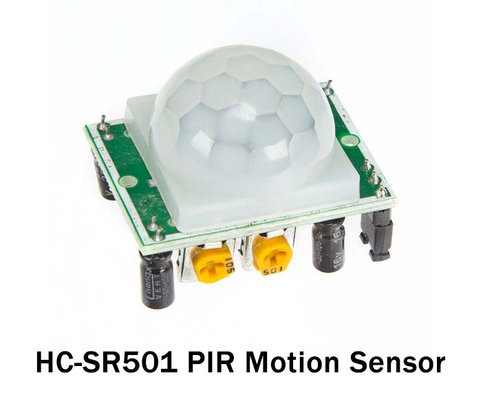
Have you seen in some modern places, the lights get turned ON when you walk or just take a step at that place. These places use motion detection sensors. One of the most widespread and inexpensive sensors for this purpose is the PIR motion detection sensor. It’s a low-powered Passive infrared sensor generally used in security devices and for automatic lighting systems. It gives notification about the movement, but not the give information about who moved. It is sometimes also called Passive infrared detectors, which is abbreviated as PID. In this tutorial, we will discover how to interface “PIR Motion Sensor with Arduino UNO”.
How does the PIR Motion Sensor Works?
The sensor has two slots in it. When there is no movement around, both the slots have the same readings. When any warm body or human is around, it inspects the heat and detects the movement. This causes a differential change between the two slots. And, output load starts its work.
Hardware Required
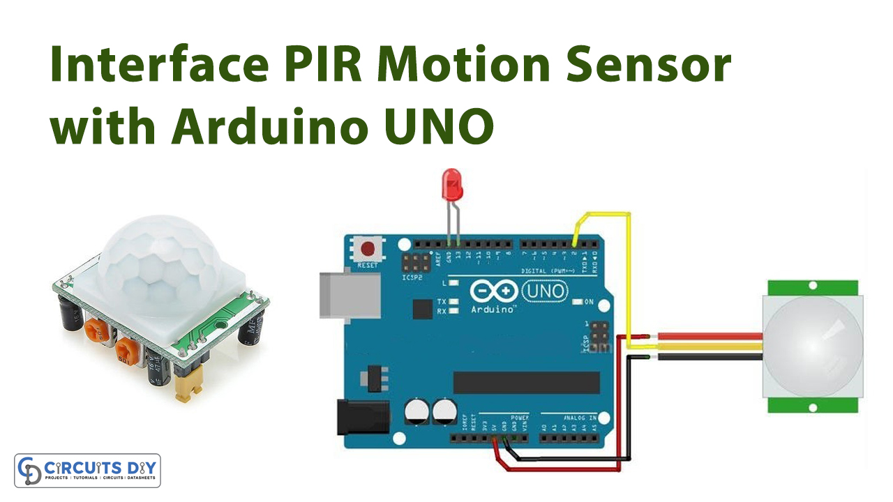
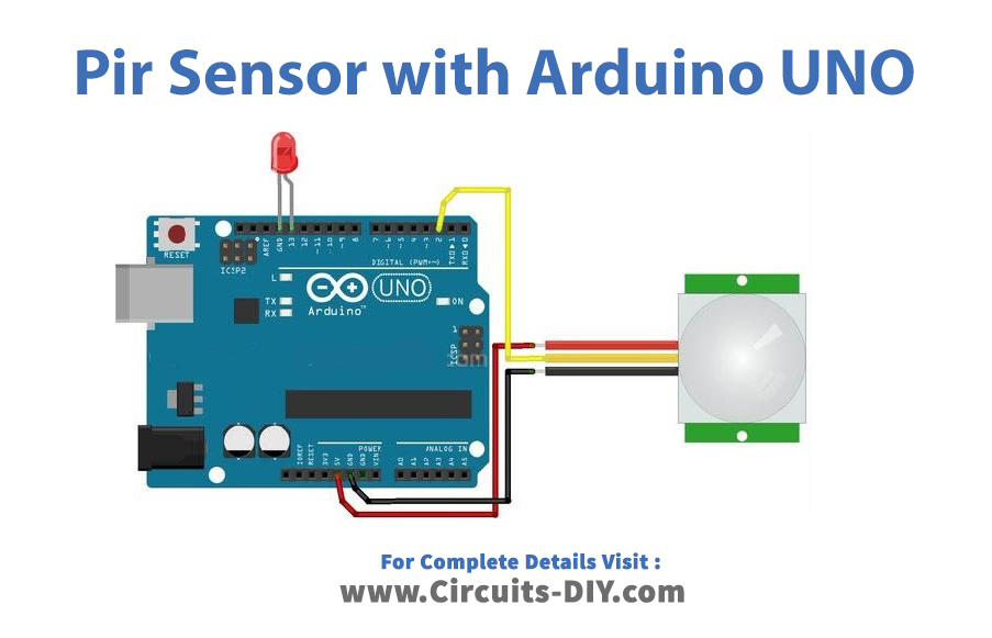
Circuit Diagram
Connection Table
| Arduino | PIR Motion Sensor |
|---|---|
| GND | GND |
| D2 | OUT |
| 5V | 5V |
Arduino Code
// Circuits DIY
// For Complete Details Visit -> https://circuits-diy.com

int led = 13;                // the pin that the LED is atteched to
int sensor = 2;            // the pin that the sensor is atteched to
int state = LOW;         // by default, no motion detected
int val = 0;                  // variable to store the sensor status (value)

void setup() {
  pinMode(led, OUTPUT);      // initalize LED as an output
  pinMode(sensor, INPUT);    // initialize sensor as an input
  Serial.begin(9600);        // initialize serial
}

void loop(){
  val = digitalRead(sensor);   // read sensor value
  if (val == HIGH) {           // check if the sensor is HIGH
    digitalWrite(led, HIGH);   // turn LED ON
    delay(100);                // delay 100 milliseconds

    if (state == LOW) {
      Serial.println("Motion detected!");
      state = HIGH;       // update variable state to HIGH
    }
  }
  else {
      digitalWrite(led, LOW); // turn LED OFF
      delay(200);             // delay 200 milliseconds

      if (state == HIGH){
        Serial.println("Motion stopped!");
        state = LOW;       // update variable state to LOW
    }
  }
}
Working Explanation
Interface the PIR motion sensor with Arduino according to the schematic that has been given above. Write and Upload the code in Arduino IDE. Now, if someone will pass through this sensor, the Arduino will read the sensor value and turned ON the LED. Also, the message appears on the Serial monitor
Code Explanation
- The code first has described the PINs of an Arduino at which the LED and sensor is connected. It also defines the state variable that keeps track of the status of the sensor using the int. And, add the variable value that holds the data coming from the .sensor
- In the void set up, it has defined that LED is an output and the sensor is an input device that is connected to the Arduino
- In the void loop, it has been defined that Arduino first read the sensor. If the value of the sensor would high, the output LED would be high. Now, the code will check the status of the sensor. Since the initial status was low, therefore it reads and prints on the Serial monitor that Motion Detected!, and then the code makes its status high. When the human body leaves the digital PIR range, the else loop starts working, and the LED will turn OFF. Seeing the state, the Serial monitor will print Motion Stopped!.
Application and Uses
- In street light circuits
- For security purpose
- In the home automation systems
- In intruder alarm circuits