Introduction
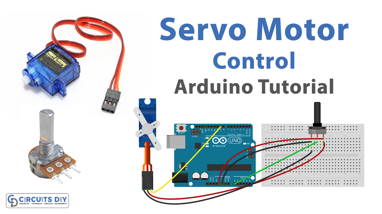
A potentiometer-controlled SG51R servo motor circuit using an Arduino Uno microcontroller is a system that utilizes the Arduino Uno microcontroller to control the position of a servo motor using a potentiometer as an input device.
The SG51R servo motor is a small, standard-sized servo motor that is commonly used in hobby and robotics projects. It is a rotary actuator that can be controlled by sending a series of pulses, which determine the position of the servo’s shaft. The SG51R servo motor can rotate from 0 to 180 degrees and can hold its position with a high level of accuracy.
Hardware Components
You will require the following hardware for Interfacing Servo Motor with Arduino.
| S.no | Component | Value | Qty |
|---|---|---|---|
| 1. | Arduino UNO | – | 1 |
| 2. | USB Cable Type A to B | – | 1 |
| 3. | Servo Motor | – | 1 |
| 4. | 9V Power Adapter for Arduino | – | 1 |
| 5. | Potentiometer | – | 1 |
| 6. | Breadboard | – | 1 |
| 7. | Jumper Wires | – | 1 |
Servo Motor with Arduino
- Include the Servo library: The Servo library should be included at the top of the code, this allows the microcontroller to control the servo motor.
#include <Servo.h>
- Initialize the pin numbers for the potentiometer and the servo motor: In the setup() function, the pin numbers for the potentiometer and the servo motor are defined using the const keyword.
const int potentiometerPin = A0;
const int servoPin = 9;
- Setup the serial communication: In the setup() function, the Serial.begin() function is used to initialize serial communication at a specific baud rate, this allows the microcontroller to communicate with the computer and post the status of the servo motor to the serial monitor.
Serial.begin(9600);
- Initialize the servo motor: In the setup() function, the Servo library’s attach() function is used to initialize the servo motor.
Servo servo;
servo.attach(servoPin);
- Read the value of the potentiometer: In the loop() function, the analogRead() function is used to read the value of the potentiometer.
int potentiometerValue = analogRead(potentiometerPin);
- Map the potentiometer value to a range of angles: In the loop() function, use the map() function to map the potentiometer value to a range of angles that the servo motor can move to.
int servoAngle = map(potentiometerValue, 0, 1023, 0, 180);
- Control the servo motor: In the loop() function, use the Servo library’s write() function to move the servo motor to the mapped angle.
servo.write(servoAngle);
- Post the status of the servo motor to the serial monitor: In the loop() function, use the Serial.print() and Serial.println() functions to send the value of the potentiometer and the angle of the servo motor to the serial monitor.
Serial.print("Potentiometer Value: ");
Serial.print(potentiometerValue);
Serial.print(", Servo Angle: ");
Serial.println(servoAngle);
- Add a delay: To prevent the serial monitor from being flooded with data, it’s a good idea to add a delay after sending the data to the serial monitor, for example, delay(100);
- Test the code: Upload the code to the Arduino UNO MCU and test the behavior of the servo motor by turning the potentiometer.
Schematic
Make connections according to the circuit diagram given below.

Wiring / Connections
| Arduino | Servo Motor | Potentiometer |
|---|---|---|
| 5V | VCC | VCC |
| GND | GND | GND |
| D9 | Yellow | |
| AO | Wiper |
Installing Arduino IDE
First, you need to install Arduino IDE Software from its official website Arduino. Here is a simple step-by-step guide on “How to install Arduino IDE“.
Installing Libraries
Before you start uploading a code, download and unzip the following libraries at /Progam Files(x86)/Arduino/Libraries (default), in order to use the sensor with the Arduino board. Here is a simple step-by-step guide on “How to Add Libraries in Arduino IDE“.
Code
Now copy the following code and upload it to Arduino IDE Software.
#include <Servo.h>
Servo myServo;  // create servo object to control a servo
void setup() {
  // initialize serial communication at 9600 bits per second:
  Serial.begin(9600);

  myServo.attach(9);  // attaches the servo on pin 9 to the servo object
}
void loop() {
  // reads the value of the potentiometer (value between 0 and 1023)
  int analogValue = analogRead(A0);

  // scales it to use it with the servo (value between 0 and 180)
  int angle = map(analogValue, 0, 1023, 0, 180);

  // sets the servo position according to the scaled value
  myServo.write(angle);

  // print out the value
  Serial.print("Analog: ");
  Serial.print(analogValue);
  Serial.print(", Angle: ");
  Serial.println(angle);
  delay(100);
}
Working Explanation
The working of the above code is as follows, the void setup() function initializes the serial communication, set the pin modes for the servo and potentiometer, and attaches the servo object to the pin that it is connected to.
The void loop() function then reads the value of the potentiometer, maps it to a value between 0 and 180, which corresponds to the range of rotation of the servo motor, uses the servo object’s write() function to set the position of the servo motor to the mapped value and sends the position of the servo motor over the serial communication using the Serial.print() function.
Applications
- 3D Printing
- Medical Devices
- Home Automation
- Science and Research.
Conclusion.
We hope you have found this Arduino Servo Motor controlling Circuit very useful. If you feel any difficulty in making it feel free to ask anything in the comment section.
Related posts:
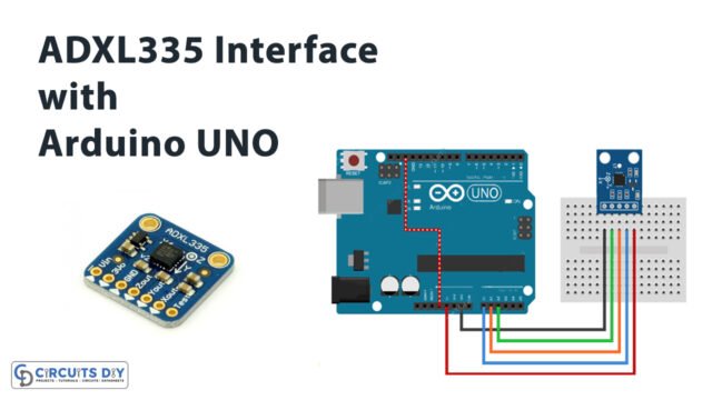 How ADXL335 Accelerometer Interface with Arduino UNO
 How to interface Vibration Sensor (SW-420) with Arduino
 Arduino High Voltage Driver Circuit Using IRF9540 Power MOSFET
 Interfacing NEO-6m GPS Module with Arduino
 Interface GT511C3 Fingerprint Scanner Module with Arduino
 Keypad with Relay - Arduino Tutorial