Introduction
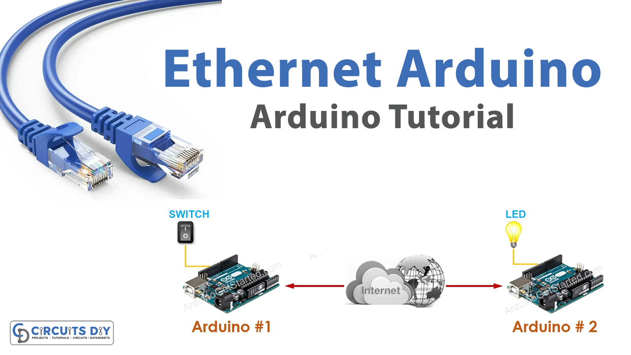
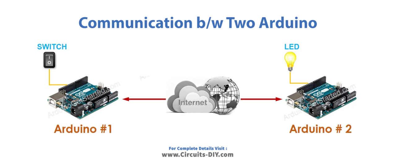
Interfacing two Arduino UNO boards with each other using a TCP/IP connection to switch on and switch off an LED is a fascinating example of how two separate devices can communicate with each other over a network. This project demonstrates the ability of the Arduino boards to communicate with each other over an Ethernet network using the TCP/IP protocol.
In this project, one Arduino board acts as a client, and the other acts as a server. The client sends commands to the server to turn the LED on or off, and the server responds accordingly. This project is an excellent way to explore the fundamentals of network communication and the capabilities of Arduino boards.
Hardware Components
You will require the following hardware for Communication between two Arduino with Arduino.
| S.no | Component | Value | Qty |
|---|---|---|---|
| 1. | Arduino | UNO | 2 |
| 2. | USB Cable Type A to B | – | 2 |
| 3. | Arduino Ethernet Shield 2 | – | 2 |
| 4. | Ethernet Cable | – | 12 |
| 5. | Power Adapter for Arduino | 9V | 1 |
Communication between two Arduino
Arduino 1:
- Include required libraries
#include <ezButton.h>
#include <SPI.h>
#include <Ethernet.h>
The code includes the libraries required for the project:
ezButton.hlibrary to handle the push-button inputSPI.hlibrary to handle the communication with the Ethernet ShieldEthernet.hlibrary to handle the Ethernet communication.
- Define the pin and port numbers
const int BUTTON_PIN = 7;
const int serverPort = 4080;
The code defines the pin number for the push-button input and the port number for the server Arduino to listen to incoming connections.
- Initialize the button object
ezButton button(BUTTON_PIN);
The code creates an instance of the ezButton class and initializes it with the pin number for the push-button input.
- Define the MAC address and server IP address
byte mac[] = {0x00, 0xAA, 0xBB, 0xCC, 0xDE, 0x03};
IPAddress serverAddress(192, 168, 0, 180);
The code defines the MAC address for the Ethernet Shield and the IP address of the server Arduino.
- Create an EthernetClient object
EthernetClient TCPclient;
The code creates an instance of the EthernetClient class to handle the TCP connection with the server Arduino.
- Set up the Arduino
void setup() {
  Serial.begin(9600);
  button.setDebounceTime(50); // set debounce time to 50 milliseconds

  Serial.println("ARDUINO #1: TCP CLIENT + A BUTTON/SWITCH");

  // Initialize Ethernet Shield:
  if (Ethernet.begin(mac) == 0)
    Serial.println("Failed to configure Ethernet using DHCP");

  // connect to TCP server (Arduino #2)
  if (TCPclient.connect(serverAddress, serverPort))
    Serial.println("Connected to TCP server");
  else
    Serial.println("Failed to connect to TCP server");
}
The setup() function sets up the Arduino:
- Starts the serial communication at 9600 baud rate.
- Sets the debounce time for the push-button input.
- Initializes the Ethernet Shield and prints a message if it fails to configure using DHCP.
- Connects to the server Arduino using the
connect()function of theEthernetClientclass and prints a message to the serial monitor indicating the success or failure of the connection.
- Handle incoming data from the server Arduino
void loop() {
  button.loop(); // MUST call the loop() function first

  if (!TCPclient.connected()) {
    Serial.println("Connection is disconnected");
    TCPclient.stop();

    // reconnect to TCP server (Arduino #2)
    if (TCPclient.connect(serverAddress, serverPort))
      Serial.println("Reconnected to TCP server");
    else
      Serial.println("Failed to reconnect to TCP server");
  }

  if (button.isPressed()) {
    TCPclient.write('1');
    TCPclient.flush();
    Serial.println("- The button is pressed,  sent command: 1");
  }

  if (button.isReleased()) {
    TCPclient.write('0');
    TCPclient.flush();
    Serial.println("- The button is released, sent command: 0");
  }
}
The loop() function runs continuously and handles incoming data from the server Arduino:
- Calls the
loop()function of theezButtonlibrary to handle the push-button input. - Checks if the TCP connection is disconnected and attempts to reconnect if necessary.
Arduino 2:
- Importing required libraries:
#include <SPI.h>
#include <Ethernet.h>
The SPI.h library provides communication support for SPI devices, and the Ethernet.h library provides networking capabilities for the Ethernet shield.
- Setting pin and port numbers:
const int LED_PIN = 7;
const int serverPort = 4080;
The LED_PIN constant sets the pin number where the LED is connected. The serverPort constant sets the port number that the server will listen on for incoming connections.
- Defining the MAC address and creating the TCP server:
byte mac[] = {0x00, 0xAA, 0xBB, 0xCC, 0xDE, 0x02};
EthernetServer TCPserver(serverPort);
The mac byte array sets the MAC address of the Ethernet shield. The EthernetServer class creates a TCP server object that listens for incoming connections on the serverPort.
- Setting up the Arduino:
void setup() {
  Serial.begin(9600);
  pinMode(LED_PIN, OUTPUT);

  Serial.println("ARDUINO #2: TCP SERVER + AN LED");

  // Initialize Ethernet Shield:
  if (Ethernet.begin(mac) == 0)
    Serial.println("Failed to configure Ethernet using DHCP");

  // Print your local IP address:
  Serial.print("TCP Server IP address: ");
  Serial.println(Ethernet.localIP());
  Serial.println("-> Please update the serverAddress in Arduino #1 code");

  // Listening for a TCP client (from Arduino #1)
  TCPserver.begin();
}
The setup() function initializes the serial communication, sets the LED pin as an output, and prints a message to the serial console. It then initializes the Ethernet shield using the Ethernet.begin() function and prints the local IP address of the Arduino. Finally, it starts listening for a TCP client by calling the begin() function on the TCPserver object.
- Handling incoming connections:
void loop() {
  // Wait for a TCP client from Arduino #1:
  EthernetClient client = TCPserver.available();

  if (client) {
    // Read the command from the TCP client:
    char command = client.read();
    Serial.print("- Received command: ");
    Serial.println(command);

    if (command == '1')
      digitalWrite(LED_PIN, HIGH); // Turn LED on
    else if (command == '0')
      digitalWrite(LED_PIN, LOW);  // Turn LED off

    Ethernet.maintain();
  }
}
The loop() function waits for an incoming connection by calling the available() function on the TCPserver object. If a client connects, the code reads the command sent by the client using the read() function on the EthernetClient object. If the command is ‘1’, the LED is turned on using digitalWrite(LED_PIN, HIGH). If the command is ‘0’, the LED is turned off using digitalWrite(LED_PIN, LOW). Finally, the Ethernet.maintain() function is called to handle any background tasks required by the Ethernet shield.
Schematic
Make connections according to the circuit diagram given below.
Installing Arduino IDE
First, you need to install Arduino IDE Software from its official website Arduino. Here is a simple step-by-step guide on “How to install Arduino IDE“.
Installing Libraries
Before you start uploading a code, download and unzip the following libraries at /Progam Files(x86)/Arduino/Libraries (default), in order to use the sensor with the Arduino board. Here is a simple step-by-step guide on “How to Add Libraries in Arduino IDE“.
Code
Now copy the following code and upload it to Arduino IDE Software.
Arduino Code for Arduino #1
#include <ezButton.h>
#include <SPI.h>
#include <Ethernet.h>

const int BUTTON_PIN = 7;
const int serverPort = 4080;
ezButton button(BUTTON_PIN);  // create ezButton that attach to pin 7;

byte mac[] = {0x00, 0xAA, 0xBB, 0xCC, 0xDE, 0x03};
IPAddress serverAddress(192, 168, 0, 180);
EthernetClient TCPclient;

void setup() {
  Serial.begin(9600);
  button.setDebounceTime(50); // set debounce time to 50 milliseconds

  Serial.println("ARDUINO #1: TCP CLIENT + A BUTTON/SWITCH");

  // Initialize Ethernet Shield:
  if (Ethernet.begin(mac) == 0)
    Serial.println("Failed to configure Ethernet using DHCP");

  // connect to TCP server (Arduino #2)
  if (TCPclient.connect(serverAddress, serverPort))
    Serial.println("Connected to TCP server");
  else
    Serial.println("Failed to connect to TCP server");
}

void loop() {
  button.loop(); // MUST call the loop() function first

  if (!TCPclient.connected()) {
    Serial.println("Connection is disconnected");
    TCPclient.stop();

    // reconnect to TCP server (Arduino #2)
    if (TCPclient.connect(serverAddress, serverPort))
      Serial.println("Reconnected to TCP server");
    else
      Serial.println("Failed to reconnect to TCP server");
  }

  if (button.isPressed()) {
    TCPclient.write('1');
    TCPclient.flush();
    Serial.println("- The button is pressed,  sent command: 1");
  }

  if (button.isReleased()) {
    TCPclient.write('0');
    TCPclient.flush();
    Serial.println("- The button is released, sent command: 0");
  }
}
Arduino Code for Arduino #2
#include <SPI.h>
#include <Ethernet.h>

const int LED_PIN = 7;
const int serverPort = 4080;

byte mac[] = {0x00, 0xAA, 0xBB, 0xCC, 0xDE, 0x02};
EthernetServer TCPserver(serverPort);

void setup() {
  Serial.begin(9600);
  pinMode(LED_PIN, OUTPUT);

  Serial.println("ARDUINO #2: TCP SERVER + AN LED");

  // Initialize Ethernet Shield:
  if (Ethernet.begin(mac) == 0)
    Serial.println("Failed to configure Ethernet using DHCP");

  // Print your local IP address:
  Serial.print("TCP Server IP address: ");
  Serial.println(Ethernet.localIP());
  Serial.println("-> Please update the serverAddress in Arduino #1 code");

  // Listening for a TCP client (from Arduino #1)
  TCPserver.begin();
}

void loop() {
  // Wait for a TCP client from Arduino #1:
  EthernetClient client = TCPserver.available();

  if (client) {
    // Read the command from the TCP client:
    char command = client.read();
    Serial.print("- Received command: ");
    Serial.println(command);

    if (command == '1')
      digitalWrite(LED_PIN, HIGH); // Turn LED on
    else if (command == '0')
      digitalWrite(LED_PIN, LOW);  // Turn LED off

    Ethernet.maintain();
  }
}
Working Explanation
n essence, the first code (Arduino #1) listens for changes in the state of the button and sends a command (a character ‘1’ when the button is pressed, and a character ‘0’ when it is released) to the second code (Arduino #2) over the Ethernet connection. The second code (Arduino #2) listens for incoming connections from Arduino #1 and reads the commands received. If the command is ‘1’, it turns the LED on, and if the command is ‘0’, it turns the LED off.
To achieve this, the code on Arduino #1 uses the ezButton library to monitor the state of the button and establish a connection to the server (Arduino #2) over Ethernet. It then sends commands over the TCP connection using the TCPclient.write() function. On the other hand, the code on Arduino #2 creates a server using the EthernetServer class, listens for incoming connections, and reads data from the connected client using the EthernetClient.read() function. It then sets the LED state according to the received command using digitalWrite() function.
Applications
- Remote monitoring and control systems
- Smart energy management systems
- Internet of Things (IoT) applications
- Robotics and automation
- Wireless sensor networks
- Smart farming and agriculture
- Smart lighting systems
- Security and surveillance systems.
Conclusion.
We hope you have found this Communication between two Arduino circuits very useful. If you feel any difficulty in making it feel free to ask anything in the comment section.