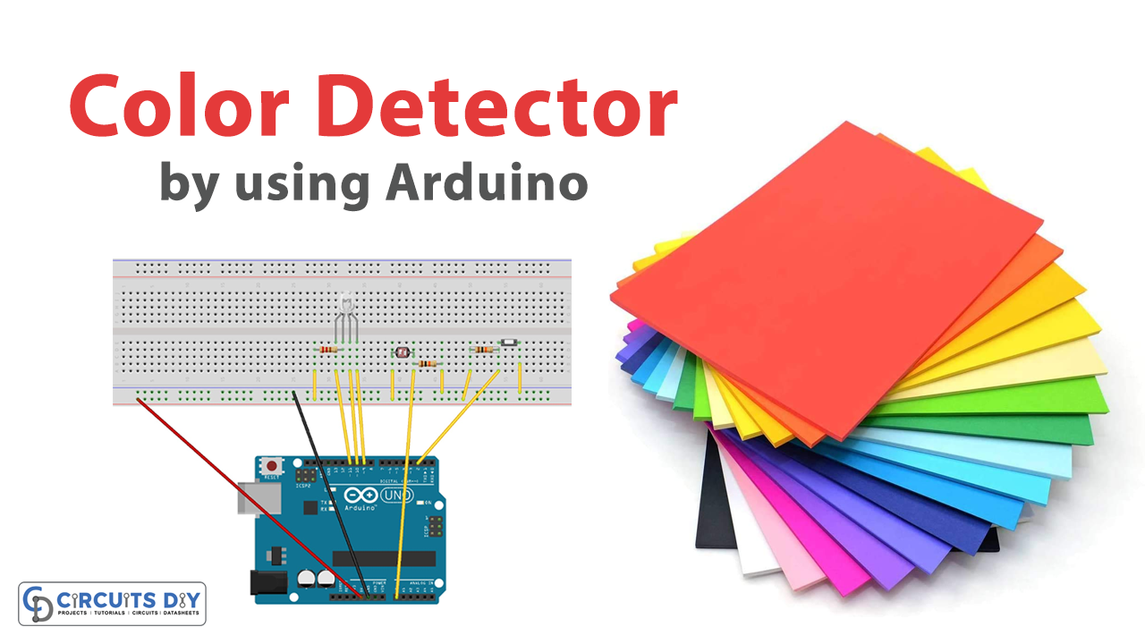
Introduction
In today’s world, colors play an important role in our lives. We see colors everywhere, from nature to technology, and being able to measure and control them is becoming increasingly important. Arduino is a versatile and user-friendly platform that allows us to measure and control various aspects of our environment, including colors. In this project, we will use a photoresistor to measure the RGB values of a color and control an RGB LED based on those values. This project will not only help us understand the basic concepts of measuring and controlling colors but also provide us with a fun and interactive way to experiment with different colors and create our own unique color palettes.
Measuring RGB values of color using a photoresistor involves understanding changes in the resistance of the photoresist based on the amount of light it receives to measure the intensity of red, green, and blue light in a given color. By measuring the intensity of each color component, the color can be accurately identified and quantified. This technique is commonly used in various applications, including color sensing, color matching, and color sorting.
Hardware Components
You will require the following hardware for the Arduino Color Detector.
| Components | Value | Qty |
|---|---|---|
| Arduino UNO | – | 1 |
| RGB LED | – | 1 |
| LDR | – | 1 |
| Resistor | 10k, 330Ω | 2, 1 |
| Switch | – | 1 |
| Breadboard | – | 1 |
| Jumper Wires | – | 1 |
Arduino Code
- Define the pins to be used for RGB LED, button, and photoresistor inputs as integer variables.
int redPin = 11;
int greenPin = 9;
int bluePin = 10;
int buttonPin = 2;
int phrPin = 0;
- Define other necessary variables as float.
float calwr, calwg, calwb, calbr, calbg, calbb, r, g, b = 0;
- Define a constant
COMMON_ANODEif a common anode LED is being used.
#define COMMON_ANODE
- Set the pinMode for each of the defined pins in
setup().
void setup(){
  pinMode(redPin, OUTPUT);
  pinMode(greenPin, OUTPUT);
  pinMode(bluePin, OUTPUT);
  pinMode(buttonPin, INPUT);
  pinMode(phrPin, INPUT);
  Serial.begin(9600);
}
- In the
loop(), read the button state, and if it is LOW, initiate calibration; if not, start measuring the color intensity.
void loop(){
  buttonState = digitalRead(buttonPin);
  if(buttonState == 0){
    Serial.println("button pressed: calibrating white");
    calibration();
  }
  else{
    measure();
  }
}
- Read the current color intensity from the photoresistor pin
phrPin.
float readColor(int times){
  float avg, total, current = 0;
  for(int n = 0; n <= times; n++){
    current = analogRead(phrPin);
    total += current;
    delay(20);
  }
  avg = total/times;
  return avg;
}
- Set the color of the RGB LED using
analogWrite(). In case of a common anode LED, invert the values of the RGB signals.
void setColor(int red, int green, int blue){
  #ifdef COMMON_ANODE
  red = 255 - red;
  green = 255 - green;
  blue = 255 - blue;
  #endif
  analogWrite(redPin, red);
  analogWrite(greenPin, green);
  analogWrite(bluePin, blue);
}
- Calibrate the photoresistor input by illuminating the RGB LED with white, and measure the color intensity.
void calibration(){
  setColor(255, 0, 0);
  delay(100);
  calwr = readColor(7);
  setColor(0, 255, 0);
  delay(100);
  calwg = readColor(7);
  setColor(0, 0, 255);
  delay(100);
  calwb = readColor(7);
  setColor(0, 0, 0);
  Serial.println("waiting to calibrate black");
  for(int i = 0; i <= 10; i+=0){
    buttonState = digitalRead(buttonPin);
    if(buttonState == 0){
      setColor(255, 0, 0);
      delay(100);
      calbr = readColor(7);
      setColor(0, 255, 0);
      delay(100);
      calbg = readColor(7);
      setColor(0, 0, 255);
      delay(100);
      calbb = readColor(7);
      setColor(0, 0, 0);
      i = 20;
    }
    else{
      //nothing
    }
  }
}
9. Declare a function called measure with no parameters:
void measure(){
  // Code goes here
}
10. Declare a variable called deltacal of type float and initialize it to 0:
float deltacal = 0;
11. Set the color of the RGB LED to red (255, 0, 0) using the setColor function:
setColor(255, 0, 0);
12. Wait for 100 milliseconds using the delay function:
delay(100);
13. Calculate the difference between the calibration values for the red and white channels, and store the result in deltacal:
deltacal = calwr-calbr;
14. Measure the value of the color sensor connected to pin 7, subtract the calibration value for the red channel, divide the result by deltacal, and multiply by 255 to get the value of the red channel. Store the result in the variable r:
r = (readColor(7) - calbr)/(deltacal)*255;
15. Set the color of the RGB LED to green (0, 255, 0) using the setColor function:
setColor(0, 255, 0);
16. Wait for 100 milliseconds using the delay function:
delay(100);
17. Calculate the difference between the calibration values for the green and blue channels, and store the result in deltacal:
deltacal= calwg-calbg;
18. Measure the value of the color sensor connected to pin 7, subtract the calibration value for the green channel, divide the result by deltacal, and multiply by 255 to get the value of the green channel. Store the result in the variable g:
g = (readColor(7) - calbg)/(deltacal)*255;
19. Set the color of the RGB LED to blue (0, 0, 255) using the setColor function:
setColor(0, 0, 255);
20. Wait for 100 milliseconds using the delay function:
delay(100);
21. Calculate the difference between the calibration values for the blue and white channels, and store the result in deltacal:
deltacal = calwb-calbb;
22. Measure the value of the color sensor connected to pin 7, subtract the calibration value for the blue channel, divide the result by deltacal, and multiply by 255 to get the value of the blue channel. Store the result in the variable b:
b = (readColor(7) - calbb)/(deltacal)*255;
23. Print the values of r, g, and b to the serial monitor, separated by commas:
Serial.print(int(r));
Serial.print(",");
Serial.print(int(g));
Serial.print(",");
Serial.println(int(b));
Schematic
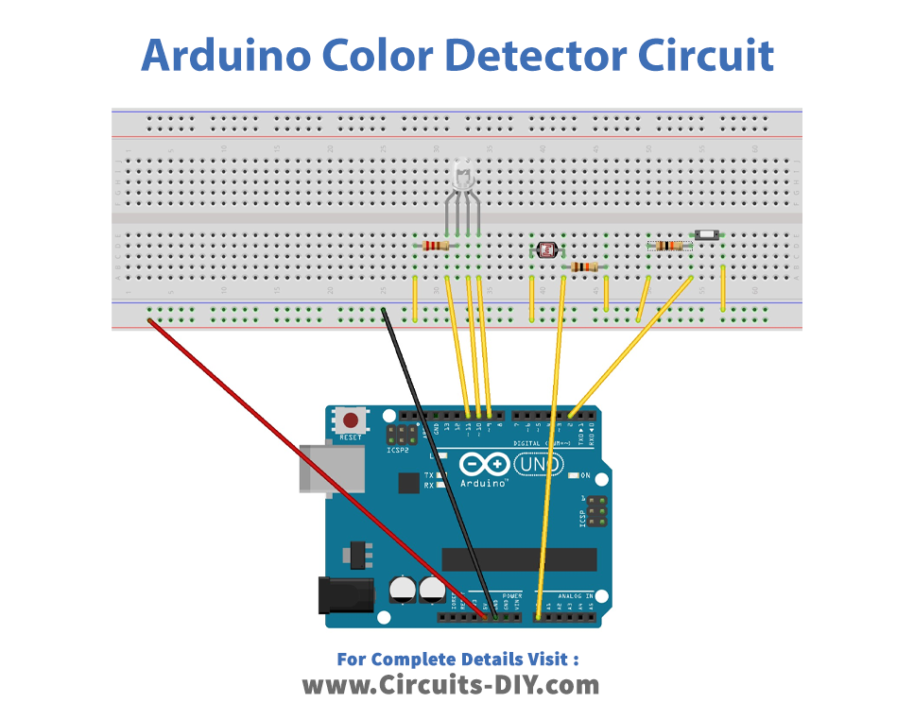
Make connections according to the circuit diagram given below.
Installing Arduino IDE
First, you need to install Arduino IDE Software from its official website Arduino. Here is a simple step-by-step guide on “How to install Arduino IDE“.
Code
Now copy the following code and upload it to Arduino IDE Software.
int redPin = 11;
int greenPin = 9;
int bluePin = 10;
int buttonPin = 2;
int buttonState = 0;
int phrPin = 0; //photoresistor pin

//other variables for calibrating and measuring
float calwr, calwg, calwb, calbr, calbg, calbb, r, g, b = 0;


//uncomment this line if using a Common Anode LED
#define COMMON_ANODE

void setup(){
  pinMode(redPin, OUTPUT);
  pinMode(greenPin, OUTPUT);
  pinMode(bluePin, OUTPUT);
  pinMode(buttonPin, INPUT);
  pinMode(phrPin, INPUT);
  Serial.begin(9600);
}

void loop(){
  buttonState = digitalRead(buttonPin);
  if(buttonState == 0){
    Serial.println("button pressed: calibrating white");
    calibration();
  }
  else{
    measure();
  }
}

float readColor(int times){
  float avg, total, current = 0;
  for(int n = 0; n <= times; n++){
    current = analogRead(phrPin);
    total += current;
    delay(20);
  }
  avg = total/times;
  return avg;
}

void setColor(int red, int green, int blue){
  #ifdef COMMON_ANODE
  red = 255 - red;
  green = 255 - green;
  blue = 255 - blue;
  #endif
  analogWrite(redPin, red);
  analogWrite(greenPin, green);
  analogWrite(bluePin, blue);
}

/*
This function is needed because the raw measure is influenced by
environmental light.
*/
void calibration(){
  //first calibrate with white color
  setColor(255, 0, 0);
  delay(100);
  calwr = readColor(7);
  setColor(0, 255, 0);
  delay(100);
  calwg = readColor(7);
  setColor(0, 0, 255);
  delay(100);
  calwb = readColor(7);
  setColor(0, 0, 0);
  //then wait until the button is pressed again
  //so we can calibrate with black color
  Serial.println("waiting to calibrate black");
  for(int i = 0; i <= 10; i+=0){
    buttonState = digitalRead(buttonPin);
    if(buttonState == 0){
      //calibrate with black color
      setColor(255, 0, 0);
      delay(100);
      calbr = readColor(7);
      setColor(0, 255, 0);
      delay(100);
      calbg = readColor(7);
      setColor(0, 0, 255);
      delay(100);
      calbb = readColor(7);
      setColor(0, 0, 0);
      i = 20;
    }
    else{
      //nothing
    }
  }
}

void measure(){
  float deltacal = 0;
  setColor(255, 0, 0);
  delay(100);
  deltacal = calwr-calbr;
  r = (readColor(7) - calbr)/(deltacal)*255;
  setColor(0, 255, 0);
  delay(100);
  deltacal= calwg-calbg;
  g = (readColor(7) - calbg)/(deltacal)*255;
  setColor(0, 0, 255);
  delay(100);
  deltacal = calwb-calbb;
  b = (readColor(7) - calbb)/(deltacal)*255;
  Serial.print(int(r));
  Serial.print(",");
  Serial.print(int(g));
  Serial.print(",");
  Serial.println(int(b));
}
Working Explanation
The code starts by defining some variables and pins used by the Arduino board, such as the pins for the RGB LED, the button pin used to calibrate the detector, and the photoresistor pin used to measure the intensity of light. Then, the code initializes the pins and starts the Serial communication at a baud rate of 9600. The loop function starts by reading the state of the button pin. If the button is pressed (buttonState == 0), the code enters the calibration function. Otherwise, it enters the measure function. The calibration function is used to calibrate the detector with white and black colors. The detector needs to be calibrated because the raw measurements are influenced by environmental light. The calibration function sets the LED to emit white light, reads the intensity of light of each primary color with the photoresistor, and saves the values as calibration parameters (calwr, calwg, and calwb). Then, it waits until the button is pressed again to calibrate with black color. The function sets the LED to emit black light, reads the intensity of light of each primary color with the photoresistor, and saves the values as calibration parameters (calbr, calbg, and calbb).
The measure function is used to measure the intensity of light of each primary color of the object being detected. The function sets the LED to emit each primary color sequentially, reads the intensity of light of each primary color with the photoresistor, calculates the intensity of the primary color as a value between 0 and 255 using the calibration parameters, and prints the values of the red, green, and blue intensities to the Serial Monitor. The setColor function is used to set the intensity of light of each primary color of the RGB LED. If the LED is a common anode type, the function needs to invert the values of the primary colors before setting them to the LED. The readColor function is used to read the intensity of light
Applications
- Educational purposes
- Color sorting
- Ambient lighting
- Art projects