Introduction
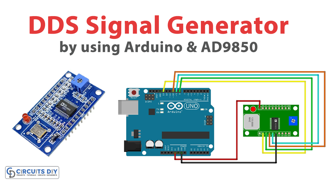
You must have used signal generators in the electronic laboratory of your elementary school, college, or university. And, we are sure that you have got a little idea of how they work and thus you came here to make your small signal generator by yourself. In this tutorial, we will “Interface AD9850 DDS Signal Generator Module with Arduino
An electronic device called a signal generator creates both repeating and non-repeating analog or digital signals. Here we are going to use the AD9850 module which generates a Direct Digital signal (DDS).
Overview of AD9850 DDS Signal Generator
This function generator has a tiny size, a compact dimension of around 4.52.61.7 cm, and can generate output waves at a frequency of 0–40 MHz with two sine wave outputs and two square wave outputs.
Hardware Overview
The AD9850 DDS Signal Generator Module includes a DSS synthesizer, a 125MHz oscillator to provide clock and timing control for the integrated circuit, and an AD9850 IC to handle all processing. The module is equipped with an internal potentiometer that can be used to change the pulse lengths and offset of the signals.
Pinouts
| Pin Name | Description |
|---|---|
| VCC | Voltage supply pin. It requires a power input of 3.3V or 5V |
| GND | Ground pin |
| W_CLK | Frequency Update. The DDS will update to the frequency placed in the data input register on the rising edge of this clock before resetting the pointer to Word 0. |
| DATA | D7, Serial Load |
| RESET | Master reset Pin |
| D0–D7 | 8-Bit Serial Data Input. |
| Square Wave Output 1 | This is the comparator’s accurate output |
| Square Wave Output 2 | This is the comparator’s complement output. |
| Sine Wave Output 1 | Analog Current Output of the DAC. |
| Sine Wave Output 2 | The analog Complementary DAC output |
Hardware Required
| S.no | Components | Value | Qty |
|---|---|---|---|
| 1 | Arduino | UNO | 1 |
| 2 | USB Cable Type A to B | 1 | |
| 3 | DDS Signal Generator Module | AD9850 | 1 |
| 4 | Jumper Wires | – |
Circuit Diagram
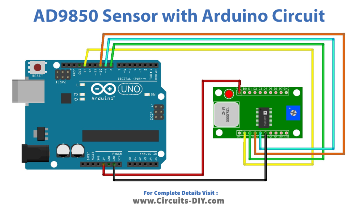
Connection Table
| Arduino | AD9850 Module |
|---|---|
| +5V | Vcc |
| D13 | W_CLK |
| D8 | FQ_UD |
| D10 | Data |
| D9 | Reset |
| GND | GND |
Arduino Code
#include <AD9850SPI.h>
#include <SPI.h>
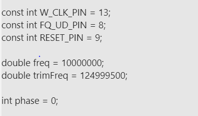
const int W_CLK_PIN = 13;
const int FQ_UD_PIN = 8;
const int RESET_PIN = 9;
double freq = 10000000;
double trimFreq = 124999500;
int phase = 0;
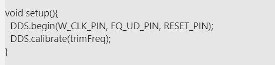
void setup(){
DDS.begin(W_CLK_PIN, FQ_UD_PIN, RESET_PIN);
DDS.calibrate(trimFreq);
}
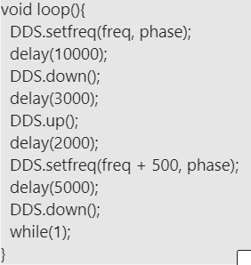
void loop(){
DDS.setfreq(freq, phase);
delay(10000);
DDS.down();
delay(3000);
DDS.up();
delay(2000);
DDS.setfreq(freq + 500, phase);
delay(5000);
DDS.down();
while(1);
}Working Explanation
The AD9850 module interface is relatively simple. To connect the AD9850 module, follow the diagram above. It needs three more pins for the RESET pins, W CLK, FU UD. Once the code has been uploaded to the Arduino, the module will start generating DDS signals.
Code Explanation
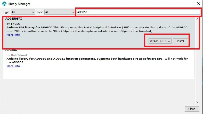
- To begin, we must install a library for the AD9850 module in the Arduino IDE. To install the library, start the Arduino IDE. Navigate to Tools >Manage Libraries. Then, in the search bar, search for AD9850. From the options, Choose AD9850 SPI and press the install button.
- Now in the code, we need to include the library. We included two libraries, one that we have installed above, and the other is the SPI library for communication. You can interface with one or more Serial Peripheral Interface devices using the SPI library.
- Next, we define the Arduino pins to which the module is connected. Then we make two objects freq and timeFreq that store the double value. Know that Arduino double has an 8-byte size. After that, we define the object phase which initially holds the 0 value of an integer
- In the void setup, we initialize the module by using the function DDS.begin. DDS.calibrate helps to calibrate the module
- Then there is a void loop that sets up the frequencies to generate the signal.
Application and Uses
- Function generator
- Signal generation for electronic projects.