Introduction
The inclinometer is the device that is utilized to estimate the movement. They are of different types, all available in the market. However, almost every tilt sensor has the same purpose. They detect when the plane shifts from horizontal to vertical plane and give the signal to the load device. They are easy to interface with. Therefore, In this tutorial, we are going to interface ” Tilt Sensor with Arduino UNO”.
Working Principle of Inclinometer
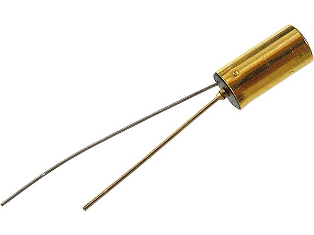
The sensor has an internal rolling ball and two conductive poles. When the sensor is entirely vertical, the ball is at the bottom of the sensor in a way that it touches the conductive poles. And, this allows the current to flow. When the sensor gets tilted, now the ball cannot touch the poles. This opens the circuit which defies the current to flow.
Tilt Sensor Features
- It has a supply voltage range from 3.3V to 5V.
- It gives the TTL output.
- The sensor draws the minimum current of 25mA.
- The sensor is easy to interface with microcontrollers.
- Cheap and reliable
- It has a great durability rate.
Hardware Required
| S.no | Component | Value | Qty |
|---|---|---|---|
| 1 | Arduino | UNO | 1 |
| 2 | USB Cable Type A to B | – | 1 |
| 3 | Jumper Wires | – | 1 |
| 4 | Tilt Sensor | – | 1 |
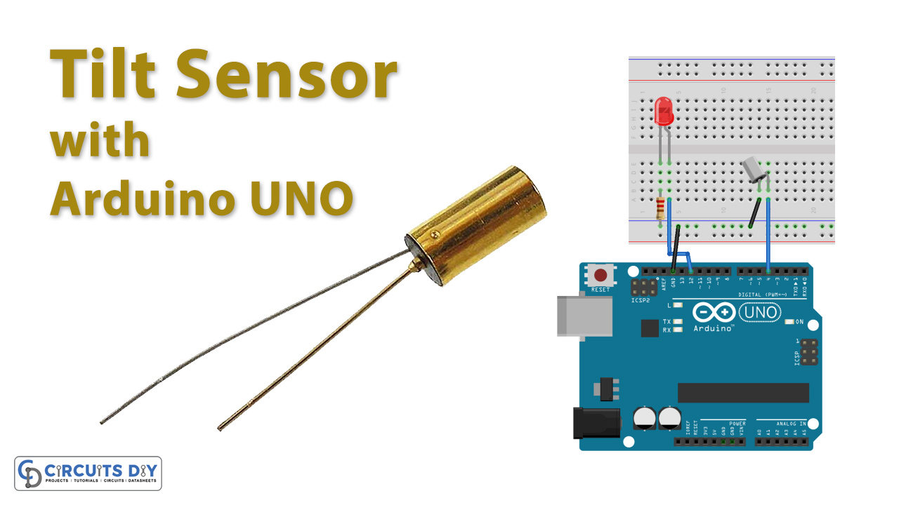
Circuit Diagram
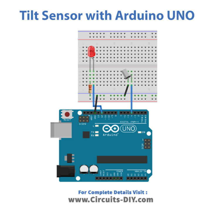
Connection Table
| Arduino | Tilt Sensor |
|---|---|
| D4 | + pin |
| GND | GND |
Arduino Code
// Circuits DIY
 // For Complete Details Visit -> https://circuits-diy.com
int ledPin = 12;
int sensorPin = 4;
int sensorValue;
int lastTiltState = HIGH;   // the previous reading from the tilt sensor

// the following variables are long's because the time, measured in miliseconds,
// will quickly become a bigger number than can be stored in an int.
long lastDebounceTime = 0;  // the last time the output pin was toggled
long debounceDelay = 50;    // the debounce time; increase if the output flickers

void setup(){
  pinMode(sensorPin, INPUT);
  digitalWrite(sensorPin, HIGH);
  pinMode(ledPin, OUTPUT);
  Serial.begin(9600);
}

void loop(){
  sensorValue = digitalRead(sensorPin);
  // If the switch changed, due to noise or pressing:
  if (sensorValue == lastTiltState) {
    // reset the debouncing timer
    lastDebounceTime = millis();
  }
  if ((millis() - lastDebounceTime) > debounceDelay) {
    // whatever the reading is at, it's been there for longer
    // than the debounce delay, so take it as the actual current state:
    lastTiltState = sensorValue;
  }
  digitalWrite(ledPin, lastTiltState);

  Serial.println(sensorValue);
  delay(500);
}
Working Explanation
Assemble the Tilt Sensor with Arduino UNO according to the above-mentioned schematic. Now, copy the above code and paste it into your Arduino IDE. Now, upload the code in the Arduino. Tilt and move the sensor to see the glowing LED.
Code Explanation
- First, we have defined the output LED pin and input sensor pin that is connected with the Arduino pins. Then, we have defined That the previous stage of the sensor was high by defining the variable LastTiltState. Then, we have define two more variables Lastdebounce time and debounceDelay.
- In the void setup, we have defined the sensor pin as the input of Arduino. And, Led as an output. Also, there we have initialized the serial monitor.
- In the void loop, we have declared the function digitalRead() to analyze the sensor reading. Then we have given the condition that if the sensor reads that value that is equal to the previous lastTiltState that we have described above, then it will reset the debouncing time. And, returns the number in milliseconds. Then, we have formulated the condition. If the condition gets verified, the lastTiltState will become the sensorValue. And, the LED pin takes the lastTiltState. The Serial. println is there to print the sensor value on the Serial Monitor
Application and Uses
- It has great use in robotics.
- It can also be used in vehicles.
- To detect the orientation.
- To sense the inclination.
Related posts:
 Control Stepper Motor with L293D Motor Driver IC & Arduino
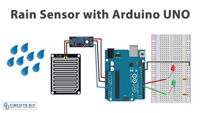 How to Interface Rain Sensor FC-37 or YL-83 with Arduino UNO
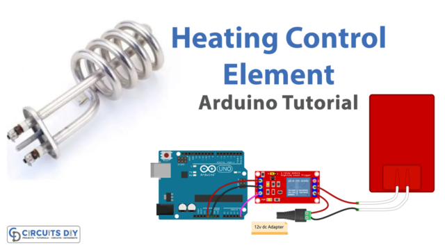 Control Heating Element - Arduino Tutorial
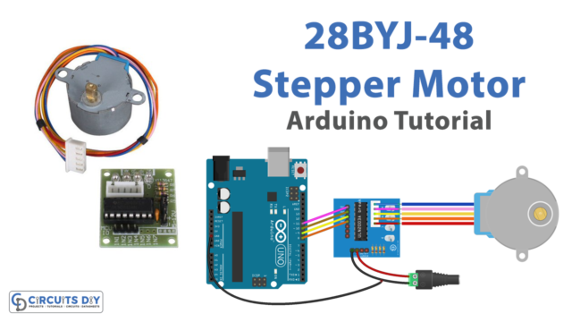 28BYJ-48 Stepper Motor Control using ULN2003 Driver & Arduino
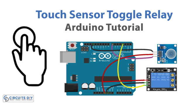 Touch Sensor Toggle Relay - Arduino Tutorial
 Door Sensor Toggle Relay - Arduino Tutorial


