Introduction
ADCs are important in electronics because they allow microcontrollers and computers to process and interpret analog signals. In many applications, sensors and other devices produce analog output signals that represent some physical quantity, such as temperature, pressure, or humidity. These analog signals need to be converted into a digital form that a microcontroller or computer can understand and process. There are different types of ADC modules available. In this article, we are Interfacing ADS1232 High Precision 24-Bit ADC with Arduino.
The interface just requires a few fundamental steps to be completed, and there is no extra circuitry that is required. As a direct consequence of this, the code is much easier to understand. Let’s not waste any more time and get to the bottom of this right now!
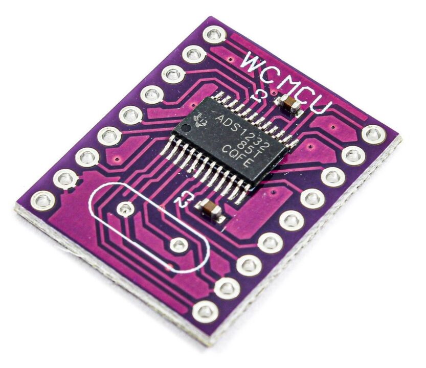
What is ADS1232?
The ADS1232 is an analog-to-digital converter (ADC) with 24 bits of accuracy. The ADS1232 is a complete front-end solution for bridge sensor applications like scales, strain gauges, and pressure sensors. It does this by having a low-noise programmable gain amplifier, a precision delta-sigma ADC, and an internal oscillator.
Hardware Components
You will require the following hardware for ABC.
| S.no | Component | Value | Qty |
|---|---|---|---|
| 1. | Arduino UNO | – | 1 |
| 2. | ADC Module | ADS1232 | 1 |
| 3. | Load Cell | 10kg | 1 |
| 4. | Breadboard | – | 1 |
| 5. | Jumper Wires | – | 1 |
Interfacing ADS1232 High Precision 24-Bit ADC with Arduino
Get all the required components that are listed above in the hardware section. Once you have them all, follow the given steps:
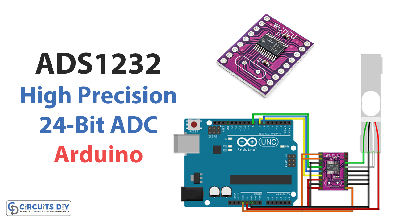
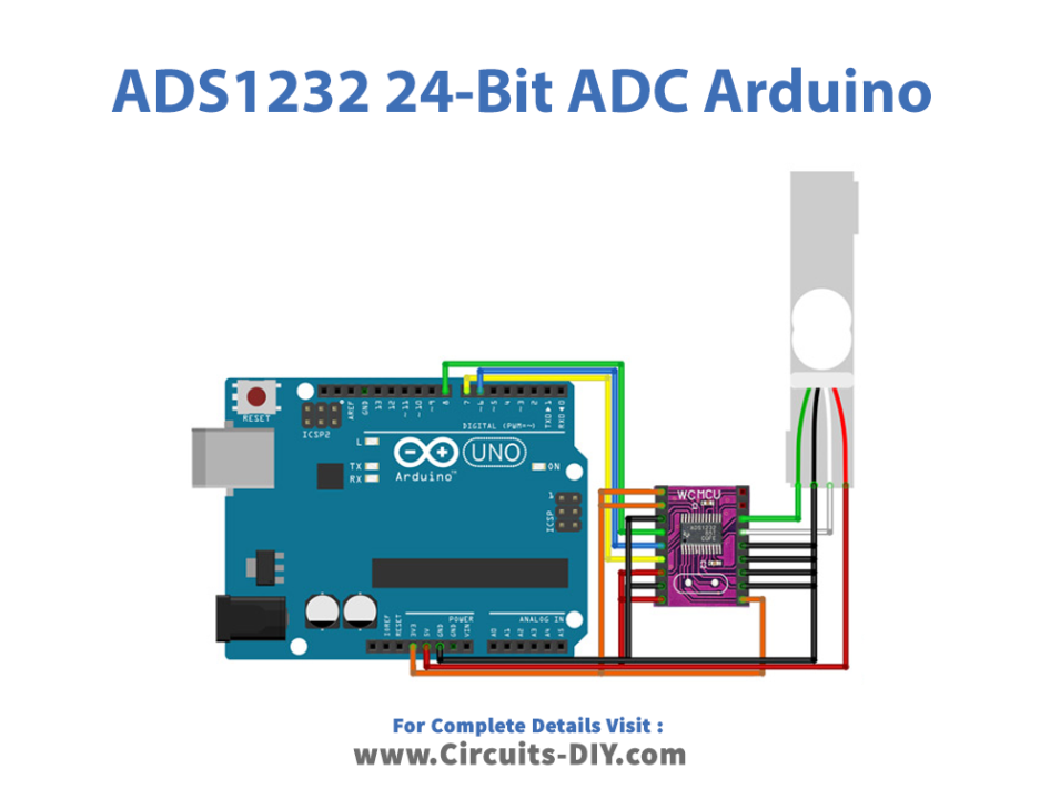
Schematic
Make connections according to the circuit diagram given below.
Installing Arduino IDE
First, you need to install Arduino IDE Software from its official website Arduino. Here is a simple step-by-step guide on “How to install Arduino IDE“.
Installing Libraries
Before you start uploading a code, download and unzip the following libraries at /Progam Files(x86)/Arduino/Libraries (default), in order to use the sensor with the Arduino board. Here is a simple step-by-step guide on “How to Add Libraries in Arduino IDE“.
Code
Now copy the following code and upload it to Arduino IDE Software.
#define _dout 6
#define _sclk 7
#define _pdwn 8

#include "ADS1232.h"

ADS1232 weight = ADS1232(_pdwn, _sclk, _dout);

void do_calibration() {
  long t_new_offset = 0;
  long t_raw_read = 0;
  float t_set_scale_value = 0;
  float t_weight = 0;

  // reset to default values
  weight.OFFSET = 0;
  weight.SCALE = 1.0;

  // tare
  t_new_offset = weight.raw_read(3);
  weight.OFFSET = t_new_offset;
  Serial.print("Calibration offset = ");Serial.println(weight.OFFSET);
  Serial.println("You have 10 seconds to put a 2L CocaCola bottle on scale");
  delay(10000);

  // do calibration based on a known weight
  t_raw_read = weight.raw_read(3);
  Serial.print("Units read = ");Serial.println(t_raw_read);
t_set_scale_value = t_raw_read / 2.0; divide it to the weight of a CocaCola bottle
  weight.SCALE = t_set_scale_value;
  Serial.print("Calibration scale value = ");Serial.println(weight.SCALE);

  // read weight
  t_weight = weight.units_read(3);
  Serial.print("Weight = ");Serial.println(t_weight);
}

void setup() {
  Serial.begin(9600);
  weight.power_up();
  do_calibration();
}

void loop() {
  Serial.println(weight.units_read(3));
  delay(1000);
*/
Let’s Test It
After you have finished uploading the code and connecting the circuit, it is necessary to test the circuit. If everything works as it should, you may go on to the next step. Open the serial monitor so you can keep an eye on the readings.
Working Explanation
Since the working of the circuit relies on the program, so let’s understand the coding first:
- This code uses an ADS1232 analog-to-digital converter (ADC) library to read weight measurements from a load cell. The ADC is connected to the Arduino using digital output, clock, and power-down pins.
- The ADC is powered up in the void setup function, and the do_calibration function is called to calibrate the ADC. The do_calibration function first resets the ADC’s offset and scale values to default values. It then performs a tare operation to determine the current weight of the load cell and sets the offset value based on this weight. Next, it waits for the user to put a known weight on the load cell and then uses this weight to calibrate the scale value. Finally, it reads the weight measurement and prints it on the serial monitor.
- In the void loop function, the units_read function is called to read in the weight measurement from the ADC, and the result is printed to the serial monitor. This is done continuously in a loop, with a delay of 1 second between readings.
Applications
- Weigh scales
- Pressure sensors, etc
Conclusion.
We hope you have found this Circuit very useful. If you feel any difficulty in making it feel free to ask anything in the comment section.