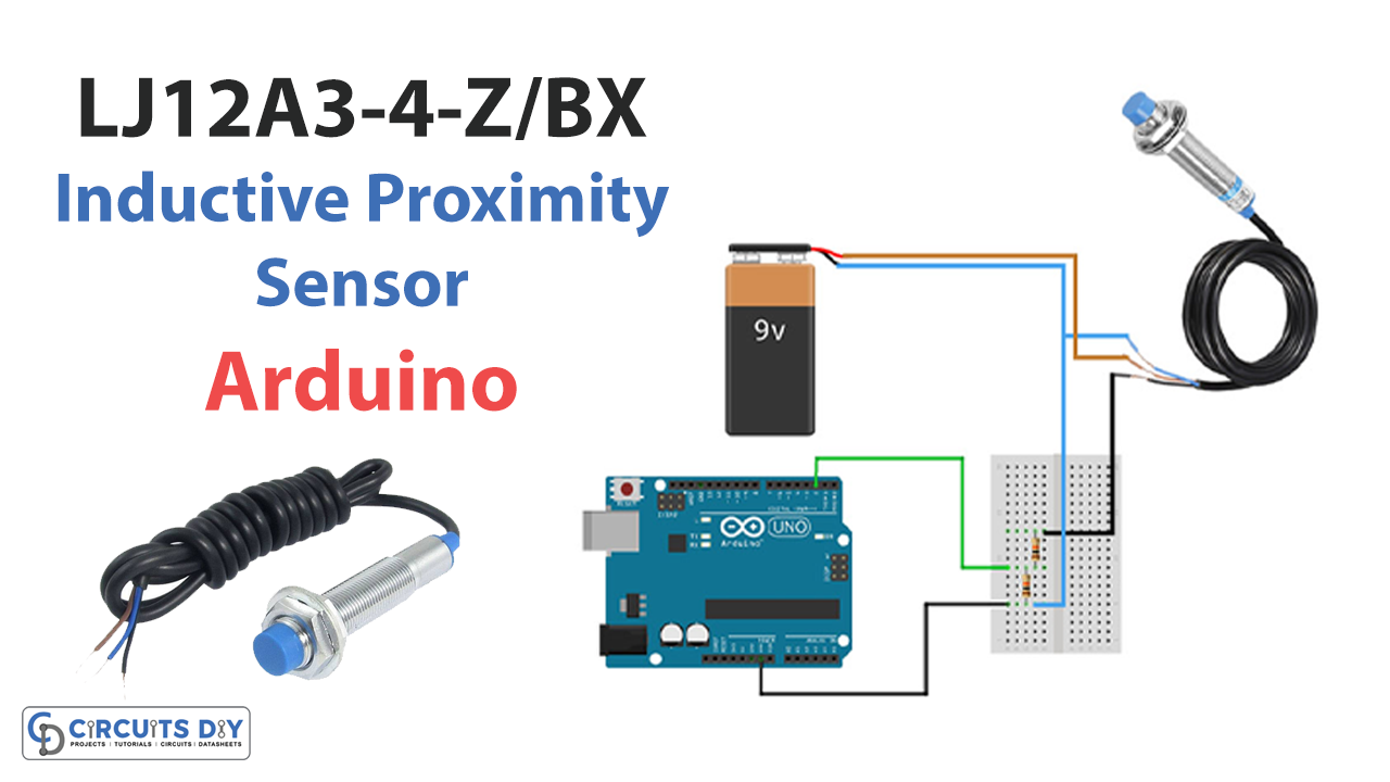
Introduction
We are sure that you have heard the name “proximity sensor,” which finds widespread usage, particularly for security management. It is also used to identify parts in automated manufacturing lines and in industrial conveyor systems. There are numerous types of proximity sensors, each of which uniquely detects targets. Capacitive and inductive proximity sensors are the two kinds used most often nowadays. In this article, we are Interfacing Inductive Proximity Sensor LJ12A3-4-Z/BX with Arduino.
Inductive proximity sensors are non-contact sensors that can detect metal items. These sensors are used to detect the closeness of metal objects. An oscillator drives a coil when an object comes close to it, following the principle of induction.
What is a Proximity Sensor?
A proximity sensor is a type of sensor that does not need physical contact and can detect the existence of an object as soon as that object enters the sensor’s region of operation.
Hardware Components
You will require the following hardware for Interfacing Inductive Proximity Sensor LJ12A3-4-Z/BX with Arduino.
| S.no | Component | Value | Qty |
|---|---|---|---|
| 1. | Arduino UNO | – | 1 |
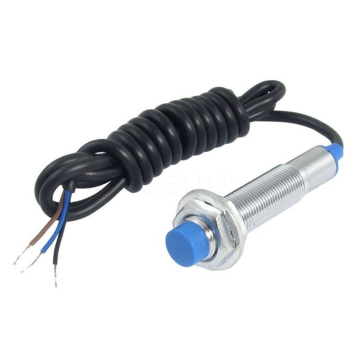
| 2. | Inductive Proximity | LJ12A3-4-Z/BX | 1 |
| 3. | Resistor | 10KΩ | 1 |
| 4. | Battery | 9V | 1 |
| 5. | 9V Battery Clips with Bare Leads | – | 1 |
| 6. | Breadboard | – | 1 |
| 7. | Jumper Wires | – | 1 |
Inductive Proximity Sensor LJ12A3-4-Z/BX with Arduino
To build the circuit, you need to follow the given steps:
Schematic
Make connections according to the circuit diagram given below.
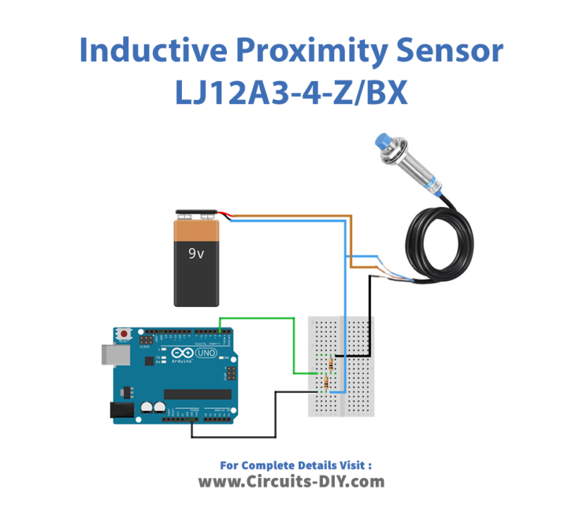
Wiring / Connections
| Arduino | Inductive Proximity | Battery |
|---|---|---|
| VCC | VCC | |
| GND | GND | GND |
| A2 | Out |
Installing Arduino IDE
First, you need to install Arduino IDE Software from its official website Arduino. Here is a simple step-by-step guide on “How to install Arduino IDE“.
Code
Now copy the following code and upload it to Arduino IDE Software.
const int Pin=2;

void setup() {
    pinMode(Pin, INPUT);
    Serial.begin(9600);
}

void loop() {
    int sensorValue = digitalRead(Pin);
    if(sensorValue==HIGH){
        Serial.println("no Object");
        delay(500);
    }
    else{
        Serial.println("Object Detected");
        delay(500);
    }
}
Let’s Test It
Once you have completed making the connections and uploading the code, its now time to test the circuit!
Place a metal object in front of the sensor and observe its performance. On the serial monitor, you’ll be able to read the messages.
Working Explanation
Let’s dive into the code to understand the working of the circuit:
- First, we define the Arduino pin connected to the sensor pin.
- After that, in the void setup function, the pin is configured as an input using the pinMode() function.
- In the void loop() function, the code reads the digital value of the pin using digitalRead() and stores it in the variable sensorValue. If sensorValue is HIGH, the pin receives no input, and the message “no Object” is printed to the serial monitor. If sensorValue is LOW, it means that the pin is receiving input, and the message “Object Detected” is printed to the serial monitor. In both cases, the program waits for some milliseconds before looping again.
Applications
- Object detection
- Security and safety devices
- Self-driving cars
- Anti-aircraft systems
- Assembly lines, etc
Conclusion.
We hope you have found this Inductive Proximity Sensor Circuit very useful. If you feel any difficulty making it feel free to ask anything in the comment section.