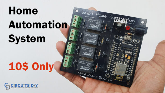
Introduction
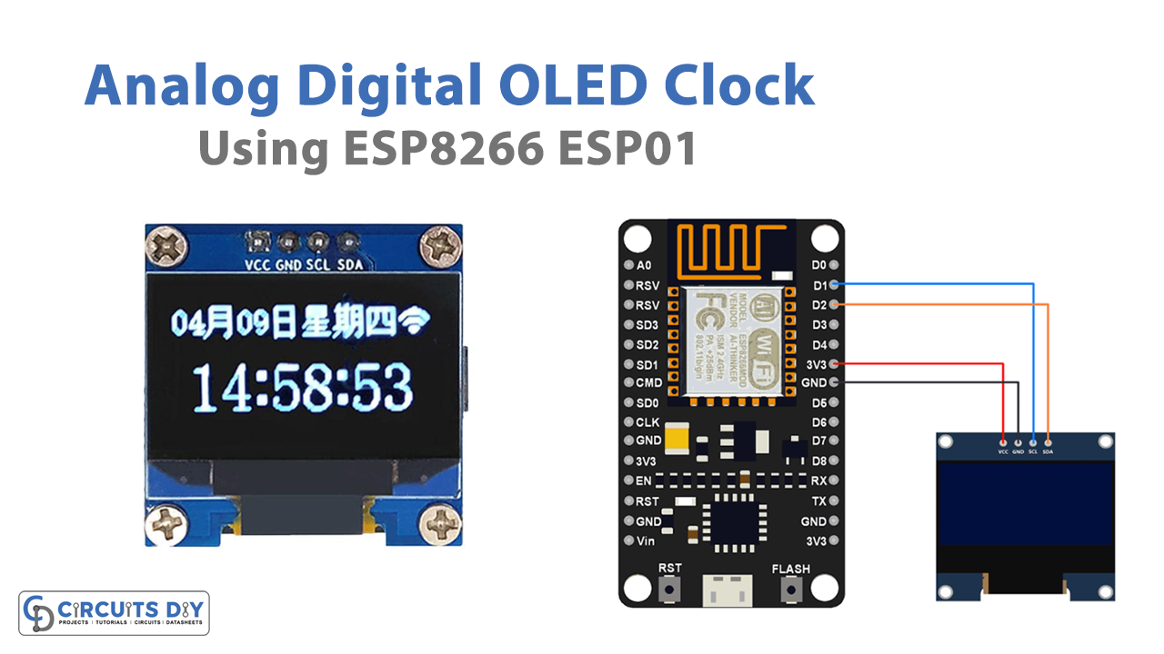
The times we are living in are all about the internet and technology. So, as the use of the internet has increased, things are also shifting towards it more and more. For example, this project talks IoT-Based Analog/Digital OLED Clock using ESP8266 ESP01. In the making of the circuit, no RTC Module is required. From an online server, the time and date would be downloaded. We have two options for displaying the downloaded time: analog or digital.
Hardware Table
| S.no | Component | Value | Qty |
|---|---|---|---|
| 1. | ESP01 | – | 1 |
| 2. | OLED Display | – | 1 |
| 3. | Connecting Wires | – | 1 |
| 4. | Breadboard | – | 1 |
Circuit Diagram

Connections
- Connect the OLED’s SCL pin to the NodeMCU’s D1 pin.
- Connect the OLED’s SDA pin to the NodeMCU’s D2 pin as well.
- Connect the 3.3V and GND pins of the OLED with the NodeMCU.
Code for Analog OLED Clock
#include <Adafruit_GFX.h>
#include <Adafruit_SSD1306.h>

#define OLED_RESET LED_BUILTIN //4
Adafruit_SSD1306 display(OLED_RESET);

const char* ssid = "AlexHome";
const char* password = "hngzhowxiantan";

int ledPin = 13;

int timezone = 7 * 3600;
int dst = 0;

#if (SSD1306_LCDHEIGHT != 64)
#error("Height incorrect, please fix Adafruit_SSD1306.h!");
#endif

void setup() {

display.begin(SSD1306_SWITCHCAPVCC, 0x3C);

// Clear the buffer.
display.clearDisplay();
display.display();

pinMode(ledPin,OUTPUT);
digitalWrite(ledPin,LOW);

Serial.begin(115200);

display.setTextSize(1);
display.setTextColor(WHITE);

display.setCursor(0,0);
display.println("Wifi connecting to ");
display.println( ssid );

WiFi.begin(ssid,password);

display.println("\nConnecting");

display.display();

while( WiFi.status() != WL_CONNECTED ){
delay(500);
display.print(".");
display.display();
}

// Clear the buffer.
display.clearDisplay();
display.display();
display.setCursor(0,0);

display.println("Wifi Connected!");
display.print("IP:");
display.println(WiFi.localIP() );

display.display();

configTime(timezone, dst, "pool.ntp.org","time.nist.gov");
display.println("\nWaiting for NTP...");

while(!time(nullptr)){
Serial.print("*");

delay(1000);
}
display.println("\nTime response....OK");
display.display();
delay(1000);

display.clearDisplay();
display.display();
}

void loop() {

time_t now = time(nullptr);
struct tm* p_tm = localtime(&now);
int r = 35;
// Now draw the clock face

display.drawCircle(display.width()/2, display.height()/2, 2, WHITE);
//
//hour ticks
for( int z=0; z < 360;z= z + 30 ){
//Begin at 0° and stop at 360°
float angle = z ;

angle=(angle/57.29577951) ; //Convert degrees to radians
int x2=(64+(sin(angle)*r));
int y2=(32-(cos(angle)*r));
int x3=(64+(sin(angle)*(r-5)));
int y3=(32-(cos(angle)*(r-5)));
display.drawLine(x2,y2,x3,y3,WHITE);
}
// display second hand
float angle = p_tm->tm_sec*6 ;
angle=(angle/57.29577951) ; //Convert degrees to radians
int x3=(64+(sin(angle)*(r)));
int y3=(32-(cos(angle)*(r)));
display.drawLine(64,32,x3,y3,WHITE);
//
// display minute hand
angle = p_tm->tm_min * 6 ;
angle=(angle/57.29577951) ; //Convert degrees to radians
x3=(64+(sin(angle)*(r-3)));
y3=(32-(cos(angle)*(r-3)));
display.drawLine(64,32,x3,y3,WHITE);
//
// display hour hand
angle = p_tm->tm_hour * 30 + int((p_tm->tm_min / 12) * 6 );
angle=(angle/57.29577951) ; //Convert degrees to radians
x3=(64+(sin(angle)*(r-11)));
y3=(32-(cos(angle)*(r-11)));
display.drawLine(64,32,x3,y3,WHITE);

display.setTextSize(1);
display.setCursor((display.width()/2)+10,(display.height()/2) - 3);
display.print(p_tm->tm_mday);

// update display with all data
display.display();
delay(100);
display.clearDisplay();

}
Code for Digital OLED Clock
#include <ESP8266WiFi.h>
#include <time.h>

#include <SPI.h>
#include <Wire.h>
#include <Adafruit_GFX.h>
#include <Adafruit_SSD1306.h>

#define OLED_RESET LED_BUILTIN //4
Adafruit_SSD1306 display(OLED_RESET);

const char* ssid = "AlexHome";
const char* password = "hngzhowxiantan";

int ledPin = 13;

int timezone = 7 * 3600;
int dst = 0;

#if (SSD1306_LCDHEIGHT != 64)
#error("Height incorrect, please fix Adafruit_SSD1306.h!");
#endif

void setup() {

display.begin(SSD1306_SWITCHCAPVCC, 0x3C);

// Clear the buffer.
display.clearDisplay();
display.display();

pinMode(ledPin,OUTPUT);
digitalWrite(ledPin,LOW);

Serial.begin(115200);

display.setTextSize(1);
display.setTextColor(WHITE);

display.setCursor(0,0);
display.println("Wifi connecting to ");
display.println( ssid );

WiFi.begin(ssid,password);

display.println("\nConnecting");

display.display();

while( WiFi.status() != WL_CONNECTED ){
delay(500);
display.print(".");
display.display();
}

// Clear the buffer.
display.clearDisplay();
display.display();
display.setCursor(0,0);

display.println("Wifi Connected!");
display.print("IP:");
display.println(WiFi.localIP() );

display.display();

configTime(timezone, dst, "pool.ntp.org","time.nist.gov");
display.println("\nWaiting for NTP...");

while(!time(nullptr)){
Serial.print("*");

delay(1000);
}
display.println("\nTime response....OK");
display.display();
delay(1000);

display.clearDisplay();
display.display();
}

void loop() {

time_t now = time(nullptr);
struct tm* p_tm = localtime(&now);

Serial.print(p_tm->tm_mday);
Serial.print("/");
Serial.print(p_tm->tm_mon + 1);
Serial.print("/");
Serial.print(p_tm->tm_year + 1900);

Serial.print(" ");

Serial.print(p_tm->tm_hour);
Serial.print(":");
Serial.print(p_tm->tm_min);
Serial.print(":");
Serial.println(p_tm->tm_sec);

// Clear the buffer.
display.clearDisplay();

display.setTextSize(3);
display.setTextColor(WHITE);

display.setCursor(0,0);
display.print(p_tm->tm_hour);
display.print(":");
if( p_tm->tm_min <10)
display.print("0");
display.print(p_tm->tm_min);

display.setTextSize(2);
display.setCursor(90,5);
display.print(".");
if( p_tm->tm_sec <10)
display.print("0");
display.print(p_tm->tm_sec);

display.setTextSize(1);
display.setCursor(0,40);
display.print(p_tm->tm_mday);
display.print("/");
display.print(p_tm->tm_mon + 1);
display.print("/");
display.print(p_tm->tm_year + 1900);

display.display();

delay(1000); // update every 1 sec

}
Working Explanation
- To precisely establish the date and time, a code that connects to an NPT time server is created using the Arduino IDE. The time and date are then shown on an OLED display as well as online using a web browser that connects to an ESP8266 webserver.
- Options like Time Zone, a 24-hour clock, Daylight Savings Time, and a variable to regulate the time server update period may all be changed on the website. Without requiring a page reload, the website uses AJAX to change the time.
- A time server is connected to the ESP8266 WiFi using the NTPClient library, and the server transmits time data to the module. Network Time Protocol (NTP).
- The Arduino Time library, which translates Unix timestamps (Unix epoch) into seconds, minutes, hours, days of the week, days, months, and years, is the last one. The duration of the Unix epoch is measured in seconds from January 1st, 1970 at midnight (UTC/GMT). The time server essentially delivers data in Unix epoch format, which has to be translated; this library takes care of everything.
- The NTPClient library is set up to obtain time information from the server time.nist.gov with an offset of 1 hour, which is equivalent to 3600 seconds, as shown below in the configuration line:
configTime(timezone, dst, "pool.ntp.org","time.nist.gov");Code Explanation
For Analog OLED
- First, we have added the required libraries. Then we defined our SSID and password. A char* is a char pointer. Then we have defined some integers. For example, ledPin defines the pin number at which LED is connected, timezone defines the time, and variable dst stores a 0 value. Then we provide the if statement for OLED.
- In the void setu, we first initialize the display by display. begin. We then give display.clearDisplay to clear the display. By using different functions we set the text size, color, and cursor. WiFi.begin is there to initialize connection with wfi. configTime(timezone, dst, “pool.ntp.org”,”time.nist.gov”)obtain time information from the server time.nist.gov. We also give the while function while(!time(nullptr); nullptr is a keyword that can be used wherever NULL is expected.
- In the void loop, we give the drawCircle function to draw the clock face (since it’s an analog clock). Then we provide a statement to give a 9 to 360 angle to our clock. After that, we defined several functions, like a function that converts degrees to radians, and the functions that make second, minute, and hour hands. In the end, we update the display with all the data by using the display.display()
For Digital OLED
- First, we added the necessary libraries. Then we established our SSID and password. A char* is a pointer to a char. After that, we defined some integers. For example, ledPin specifies the pin number to which the LED is connected, timezone specifies the time, and variable dst has a value of zero.
- In void setup, Display. begin is used to initialize the display. To clear the display, we use display.clearDisplay. We change the text size, color, and cursor by utilizing various functions. WiFi.begin is used to establish a wireless connection. configTime(timezone, dst, “pool.ntp.org”, “time.nist.gov”) is used to receive time information from the server time.nist.gov. While(!time(nullptr); nullptr is a keyword that may be used whenever NULL is anticipated is also provided.
- In the void loop, we give the functions to make the clock look digital. There is programming to display seconds, minutes, hours, days, years, etc.
Application and Uses
- It can be utilized in IoT-based applications.
- IoT smart alarm clock, etc.