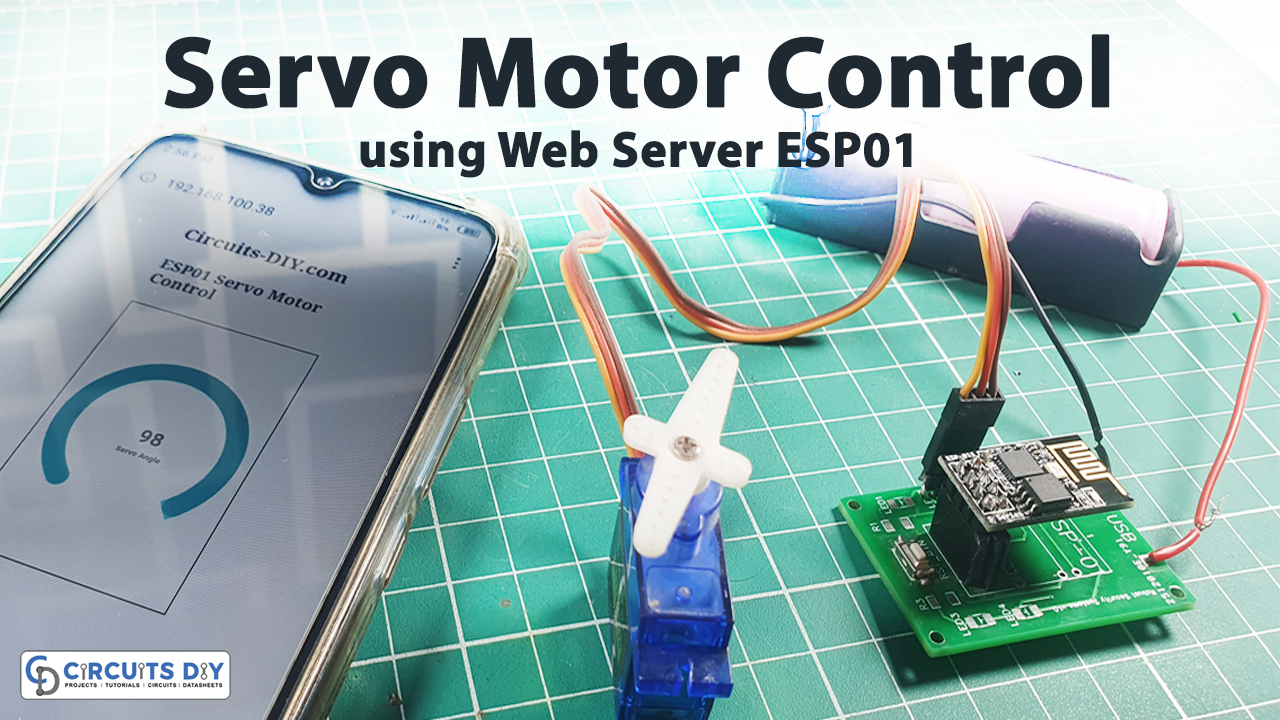
Introduction
Controlling servo motors with different controllers and circuits is quite an easier thing which we have discussed in our various articles. However, controlling the same Servos using a web server might be a new thing for you. Thus, trying new things is always fun. So, here we are with the project ESP01 Servo Motor Control using a Web Server. Hence for making this project we are using the esp01 wifi module.
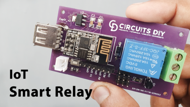
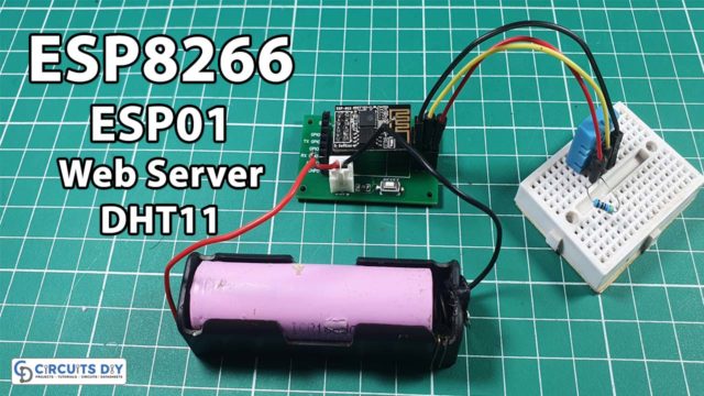
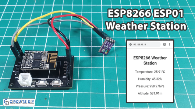
An Overview of ESP01 wifi module
ESP01 is a WiFi module that allows a microcontroller to connect to a WiFi network with ease. It incorporates antenna switches, power amplifiers, and power executive features, making it one of the most widely used WiFi chips in the industry.
This module has minimal internal circuitry, and the complete solution, including the front-end module, is designed to take up the smallest amount of PCB space possible. The ESP-01 module is referred to as a system on chip (SOC) since it functions as a standalone microcontroller that does not require the use of any other microcontrollers.
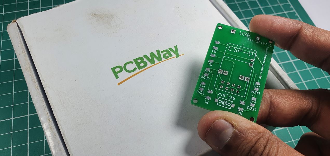
PCBWay commits to meeting the needs of its customers from different industries in terms of quality, delivery, cost-effectiveness, and any other demanding requests. As one of the most experienced PCB manufacturers in China. They pride themselves to be your best business partners as well as good friends in every aspect of your PCB needs.
Hardware Components
The following components are required to make the ESP01 Servo Motor Control Circuit
| S.no | Component | Value | Qty |
|---|---|---|---|
| 1. | Module | ESP01 | 1 |
| 2. | Servo Motor | – | 1 |
| 3. | Cell | 3.7V | 1 |
| 4. | Arduino | UNO | 1 |
| 5. | Connecting Wires | – | 1 |
ESP01 Servo Motor Control Circuit

Arduino Code
#include
#include
#include
#include "index.h";
#define LED 2
#define ServoPin 1

//WiFi Connection configuration
const char *ssid = "Circuits DIY";
const char *password = "03433212601";

Servo myservo;  // create servo object to control a servo
// twelve servo objects can be created on most boards

ESP8266WebServer server(80);

void handleServo(){
  String POS = server.arg("servoPOS");
  int pos = POS.toInt();
  myservo.write(pos);   // tell servo to go to position
  delay(15);
  Serial.print("Servo Angle:");
  Serial.println(pos);
  digitalWrite(LED,!(digitalRead(LED))); //Toggle LED
  server.send(200, "text/plane","");
}

void handleRoot() {
 String s = MAIN_page; //Read HTML contents
 server.send(200, "text/html", s); //Send web page
}

void setup() {
  delay(1000);
  Serial.begin(115200);
  Serial.println();

  pinMode(LED,OUTPUT);
  myservo.attach(ServoPin); // attaches the servo on GIO2 to the servo object

  //Connect to wifi Network
  WiFi.begin(ssid, password);     //Connect to your WiFi router
  Serial.println("");

  // Wait for connection
  while (WiFi.status() != WL_CONNECTED) {
    delay(500);
    Serial.print(".");
  }

  //If connection successful show IP address in serial monitor
  Serial.println("");
  Serial.print("Connected to ");
  Serial.println(ssid);
  Serial.print("IP address: ");
  Serial.println(WiFi.localIP());  //IP address assigned to your ESP

  //Initialize Webserver
  server.on("/",handleRoot);
  server.on("/setPOS",handleServo); //Sets servo position from Web request
  server.begin();
}
void loop() {
 server.handleClient();
}
Working Explanation
First, connect the circuit and burn the program. The main program is in charge of connecting the ESP01 to WiFi, retrieving data from the web, and finally operating the Servo. If you access the serial monitor once the code has been uploaded, you can view the status of the ESP01 WiFi Module. After you’ve completed all of the initialization procedures, you may go on to Web Control.
Code Explanation
- We first included the required libraries, including servo and esp libraries. Also, we have used an index.h library to connect to a wifi network.
- Then we have defined that LED is connected to pin 2 and the servo pin to pin 1.
- To set the wifi configuration, we have defined two variables that store the characters including name and password.
- After that, we made the servo object myservo that stores the servo readings.
- On port 80, we build a server instance that listens for HTTP requests. For web servers, this is the default port.
- In void handleServo, where we handle the servo control, we have defined the variable POS that stores the string value. We then defined another variable pos. Here we have used POS.toInt() which converts the string into an integer and stores it in the variable pos. Then myservo.write(pos) write the value to the servo. After that program prints the angle and pos value. And, for this, we have used the Serial.println function. Then we write the digitalWrite(LED, !(digitalRead(LED))) function to toggle our LED
- In the void handleRoot, we first made the variable that stores the string data having HTML content. Then we used the function server.send which returns the data of the connected client.
Void Setup and Void loop
- In the void setup, we have declared LED as output, we have used the servo.attach to attach the servo variable to the pin at which the servo is connected. Then to connect the circuit to the wifi, we used the WiFi.begin function that has id and password as Its parameter. To wait for the connection to build we have used the while condition. If the connection gets successful, it will print some strings including your Ip address. We then set the servo position by using the server.on(“/setPOS”, handleServo). Then, to initialize the webserver we used a server.begin function.
- In the void loop, to monitor the presence of the client and delivers the HTML page, we have used server.handleclient().
Application and Uses
The goal of ESP01 Servo Motor Control using a Web Server is to create a web-controlled device that allows you to operate it via the internet. This application can be expanded to more advanced and demanding applications, such as remotely commanding a robot.
.