Introduction
Are you interested in robotics and electronics? If so, you might be familiar with the concept of a “line-follower robot”—a simple yet fascinating machine that can navigate a path by following a line on the ground. But how does this robot know where to go and how to adjust its course? The answer lies in a clever electronic circuit that uses light sensors, amplifiers, and transistors to control the robot’s movements.
In this blog, we’ll take a closer look at the workings of a simple line follower circuit, including the role of op-amps. We’ll also explore some practical applications of line-follower robots, from industrial automation to educational toys. So, get ready to discover the secrets of this fascinating circuit and unleash your creativity!
Hardware Required
You will require the following hardware for the Line Follower Circuit.
| S.no | Components | Value | QTY |
|---|---|---|---|
| 1 | IC | LM324 | 1 |
| 2 | Resistor | 1k, 100, 100k, 220, 10k | 5,2,4,2,5 |
| 3 | LDR Transmitter | – | 1 |
| 4 | LDR Receiver | – | 1 |
| 5 | Battery | 9v | 2 |
| 6 | Transistor | 2N3906, 2N2222 | 1, 1 |
| 7 | LED | – | 2 |
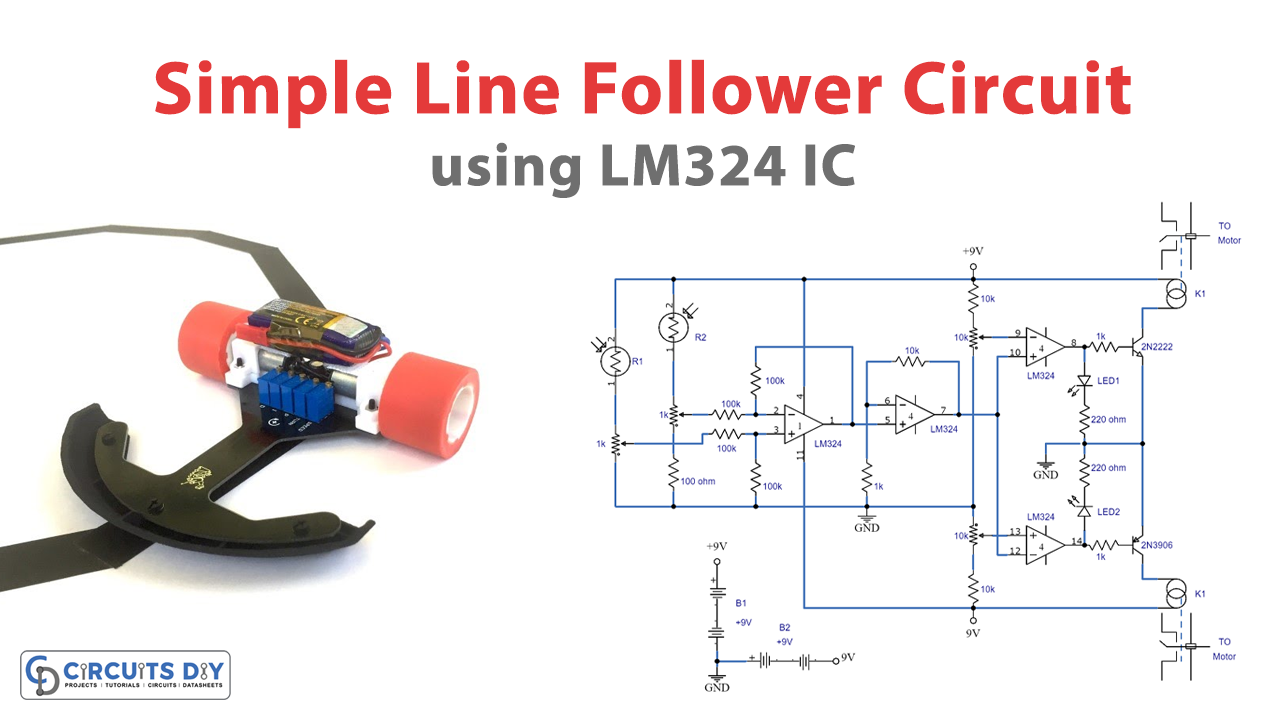
Circuit Diagram

Working Explanation
The circuit employs four operational amplifiers from the IC LM324. Here is how the circuit works:
Differential Comparator
The U1a op-amp in the circuit is configured as a differential comparator, with both inputs connected to light-dependent resistors (LDRs). The LDRs are connected via adjustable presets calibrated so that the LDRs produce uniform responses on the op amp’s input terminals when the light level is uniform on the LDRs. However, if one LDR receives more light than the other, it creates a voltage difference on pin 3 of the op-amp, resulting in a positive output from U1a. Conversely, if the other LDR receives more light, the output of U1a becomes negative. Therefore, the output of U1a switches between high and low logics based on the differences between the light levels on the LDRs.
Voltage Follower and Amplifier
The U1b op-amp in the circuit is simply a voltage follower and amplifier that tracks and amplifies the varying signals from the U1a output.
Driver Op Amps
The next two op amps, U1c and U1d, are configured as driver op-amps. When a positive signal is detected from the LDR comparators, indicating increased light on one LDR, the non-inverting inputs of U1c and U1d become positive, causing their outputs to turn high. This high output from both op amps causes Q1 to conduct since it is an NPN transistor. However, Q2 remains switched OFF since it is a PNP transistor. Q1 switches on the connected relay, toggling its contacts so that one of the relevant motors switches OFF momentarily, correcting the vehicle or line follower robot’s orientation so that both LDRs receive the same amount of light.
In the other scenario, if the other LDR receives more light, it causes a negative voltage to develop on the non-inverting inputs of U1c and U1d. This causes their outputs to turn negative or 0 volts. Consequently, the NPN transistors do not respond to the negative signal, but the PNP transistor responds and toggles its own connected relay. The relay contacts switch accordingly and momentarily switch off the relevant motor until the line follower car or robot adjusts automatically and corrects the light level on the LDRs, enabling the vehicle to run parallel with the line and follow it faithfully.The circuit employs four operational amplifiers from the IC LM324. Here is how the circuit works.
Applications
- Industrial automation: Line follower robots can be used in factories and warehouses to transport goods or materials along a predetermined path. They can also be programmed to avoid obstacles and adjust their speed or direction.
- Education and research: Line follower robots are a popular tool for teaching robotics and electronics, as they are relatively easy to build and program. We can also use them in research projects to explore the principles of automation and control.
- Entertainment: Line follower robots can be used as toys or interactive exhibits in museums, science fairs, and other public events. They can be programmed to follow different patterns or colors or to interact with the audience in various ways.
- Agriculture and environment: Line follower robots can monitor crop growth, detect weeds, or map the terrain in agricultural or environmental settings. We can also use them to collect samples or data in hazardous or inaccessible areas.
- Home automation: Line follower robots can be adapted for use in smart homes, where they can navigate around obstacles and perform various tasks such as cleaning, monitoring, or entertainment.
- Sports and competitions: Line follower robots are often used in robotics competitions and contests, where they compete against each other in speed, accuracy, or complexity. They can also be used in sports events like robot races or soccer matches.
These are just a few examples of the many applications of a simple line follower circuit. As technology advances and new challenges arise, we expect to see even more innovative and creative uses of this versatile circuit.
Final Words
A simple line-follower circuit can be a fun and educational project for anyone interested in robotics and electronics. With just a few essential components, you can build a robot or a car that can follow a line on the floor or a track and perform various tasks or challenges. So, if you’re looking for a new project or challenge, why not try building a line follower circuit and see where it takes you? Who knows, you might discover a new talent, passion, or career path that you never thought possible. Happy building!