Nowadays in the field of electronics, wireless power transmission is the most wanted and demanding technology. It is a process to supply power via airgap, without any physical connection. There are two parts to it, the transmitter and the receiver. The transmitter generates a high-frequency electromagnetic field that transmits power to the receiver without any physical connection. Then the receiver extracts the magnetic field to the electrical load. Several types of wireless energy methods are being tested and prototypes are made out of them. The most popular application of this is the wireless mobile charging system. Here in this article, we design a wireless gadget / mobile charging device.
How does Wireless Energy Transfer work?
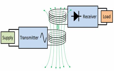
In near-field inductive coupling, a pair of coils is used to transfer energy in the form of magnetic fields from the transmitter (TX) coil to the receiver (RX) one. But it is possible only for a few inches, it may increase in near future.
Here as we can see in the block diagram, to provide biasing to the oscillator circuit and switching device the DC power source is used. This circuit converts the DC supply into a high-frequency switching pulse. These pulses are converted into magnetic flux, as soon as they reach the Tx-Coil. Here as Rx-Coil is placed near to the Tx-Coil, that produced magnetic flux induces the Rx-Coil. Because of this, alternate energy is produced by Rx-coil. Then rectification circuit makes direct current output from the Rx-coil energy. In the end voltage/Current regulation circuit is placed to limit energy and applied to the target device.
Hardware Required
| S.no | Component | Value | Qty |
|---|---|---|---|
| 1. | NPN Transistor | BD139 | 1 |
| 2. | Resistor | 5KΩ,1KΩ | 1,1 |
| 3. | Capacitor | 1nF,0.7nF,0.22uF,0.01uF,100uF/25V,1uF/10V | 1,1 |
| 4. | LED | – | 1 |
| 5. | IC | LM7805 | 1 |
| 6. | Diode | 1N4007 | 4 |
| 7. | 20 SWG Enameled Copper Wire 6 CM dia and 5 turns with a Center Tap in the Middle | – | 1 |
| 8. | Connecting Wires | – | – |
| 9. | Battery | 9V | 1 |
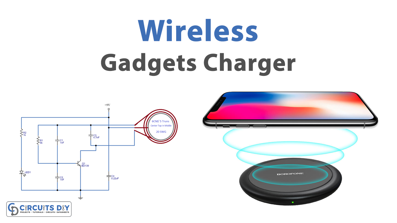
Transmitter Circuit Diagram
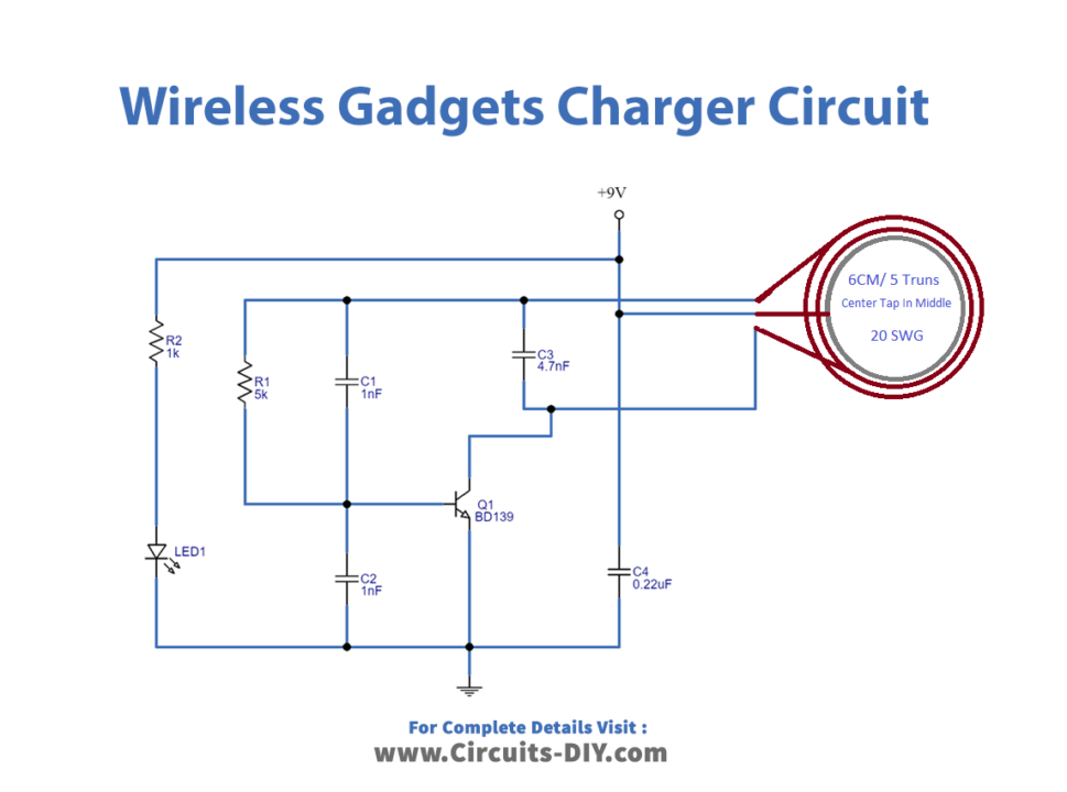
Working Explanation
Here we try to construct a circuit that can provide high-frequency magnetic flux. As shown in the diagram, first we need a center-tapped coil that we can make through 20 SWG enameled copper wire 6 CM diameter and 5 turns with a center tap in middle. Then a BD139 NPN transistor is placed, it reacts as a switching device and oscillates high-frequency signal with the help of R1, C1, and C2 Resonator elements. Now LED 1 is used to indicate the presence of bias in this circuit.
Receiver Circuit Diagram
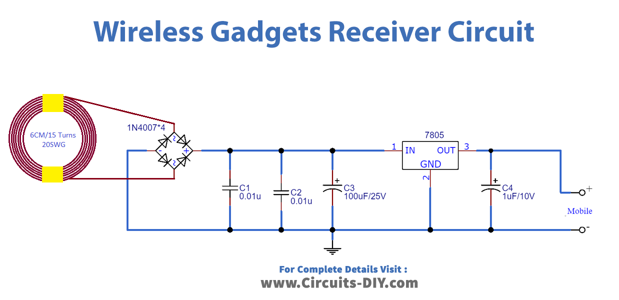
Working Explanation
Here in this circuit, 20 SWG enameled copper wire 6 CM diameter 15 turns coil is connected to the bridge rectifier (1N4007 X 4). Then the filter capacitors C1, C2, and C3 are connected across the output terminals of the bridge rectifier. Further, an IC 7805 positive voltage regulator is placed to provide regulation to the DC supply from the rectifier. Now, this regulated output supply is ready to charge your gadgets / mobile battery. Make sure about Gadgets / Mobile battery specifications and output characteristics V / I of this circuit before starting charging.
Applications
- DC Fans
- Helps in making Waterproof Products
- Wireless Lamp