Suppose you have finally built your ideal home theater and decided to keep all the cables somewhere. You do not want cables under your television since it would be unmanageable, and the wires would be a mess. You then place it in a nearby cabinet or a little farther away, depending on your preference. Here’s the problem: remote controls rely on Infrared signals for communication, and IR signals can’t penetrate objects and often fail when there’s interference in their path. Thus, they can’t penetrate the cable box.
Using an IR remote control extender is the best way to solve this issue. Because an IR extender can deliver the infrared signal sent from your remote control, you can still manage your home theater system even if it is not in direct view.
What is IR Remote Extender?
An infrared remote (IR) extender, also known as a repeater, is equipped with a receiver that is meant to pick up the infrared signal transmitted by your remote control and then send it to the device being controlled through the use of radio waves.
Hardware Required
| S.no | Components | Value | Qty |
|---|---|---|---|
| 1. | IC | CD4049 | 1 |
| 2. | Transistor | BC109C | 1 |
| 3. | IC | LM7805 | 1 |
| 4. | IR receiver | TSOP1736 | 1 |
| 5. | IR LED | – | 2 |
| 6. | Capacitor | 0.1uF | 2 |
| 7. | Resister | 33Ω, 1KΩ, 3.3KΩ, 10KΩ | 1,1,1,1 |
| 8. | 2-Pin Connector | – | 1 |
Circuit Diagram
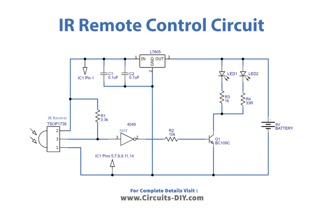
Working Explanation
In this IR Remote Control Extender Circuit, to detect the IR beam transmitted by remote control, an IR receiver called TSOP 1736 is utilized. The output from this sensor is supplied into the not gate, and the output that has been inverted is connected to the base of the transistor Q1. This NPN transistor functions as a switch and the IR LEDs wired to it generate an IR beam based on the received data.
Application and Uses
- Television
- Remote control lights
- Home theatrical systems