In this tutorial, we are going to Make “SW-420 Vibration Sensor Module Interfacing with Arduino”
Brief Overview
Sw-420 is a non-directional vibration sensor. When a force is applied, a vibration or sufficient velocity is brought to bear. It converted the terminals’ conductivity to ON-State. The module includes a comparator LM393 and a potentiometer for fine-tuning, so when the vibration is less than the sensor’s predetermined value, the sensor output is in a high condition.
Hardware Overview
- In this vibration sensor module, the voltage comparator is an LM393 Comparator IC. It connects to pin 3 of the LM393’s IC to the vibration sensor while connecting pin 2 to the potentiometer. The preset pin 2 and the vibration sensor pin 3 are used by the comparator IC to compare the specified threshold voltage.
- There is an onboard potentiometer that may be used to modify the threshold sensitivity of the digital output.
- They constructed the vibration sensor out of a tiny device that makes a touch when the vibration rises over a specific level. The potentiometer controls the value.
- Two LEDs are on the module. When the module is powered on, one will glow, and the other will show the digital output.
Pinout
| Pin Name | Description |
| VCC | The VCC pin powers the module, typically with +5V |
| GND | Power Supply Ground |
| DO | Digital Out Pin for Digital Output |

Hardware Required
| S.no | Component | Value | Qty |
|---|---|---|---|
| 1. | Arduino UNO | – | 1 |
| 2. | USB Cable Type A to B | – | 1 |
| 3. | Vibration Sensor Module | SW-420 | 1 |
| 4. | Jumper Wires | – | – |
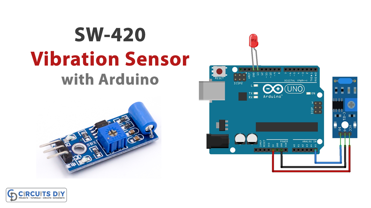
Circuit Diagram

Connection Table
| Arduino UNO | SW-420 Vibration Sensor Module |
|---|---|
| GND | GND |
| 5v | Vcc |
| A5 | D0 |
Arduino Code
#include <Arduino.h>
#include <stdio.h>

//define on/off logic symbols with name ON and OFF
#define ON HIGH
#define OFF LOW

#define Sensor_Out_Pin A5
#define LED_Pin  13

int present_condition = 0;
int previous_condition = 0;

void setup() {
pinMode(Sensor_Out_Pin, INPUT);
pinMode(LED_Pin, OUTPUT);
}


void LED_Pin_blink(void);

void loop() {
previous_condition = present_condition;
present_condition = digitalRead(Sensor_Out_Pin); // Reading digital data from the A5 Pin of the Arduino.

if (previous_condition != present_condition) {
LED_Pin_blink();

} else {
digitalWrite(LED_Pin, OFF);
}
}

void LED_Pin_blink(void) {
digitalWrite(LED_Pin, ON);
delay(250);
digitalWrite(LED_Pin, OFF);
delay(250);
digitalWrite(LED_Pin, ON);
delay(250);
digitalWrite(LED_Pin, OFF);
delay(250);
}
Working Explanation
After making the connections, Upload the code in Arduino. Make some vibrations by touching the surface where the module is placed or by moving the module while observing the LED. You will observe that when the vibration sensor module detects vibrations, the LED begins to blink to alert us.
Code Explanation
- First, we Include libraries. The code shown above was created using the Eclipse IDE program and the Arduino extension. As a result, we must include the “Arduino.h” header file. If the code is created in the Arduino IDE, there is no need for an Arduino.h header file. Two macros for two constants are defined at the beginning of the sketch. ON equals 1 and OFF equals 0. We must define pins for the Arduino to receive the data from the sensor and show it via the LED after processing. As a result, A5 and D13 of the Arduino are connected. Two integer type variables—prior condition and present condition—that store the current and previous data are defined and initialized in order to compare the values.
- In the void setup, the pin mode or direction is specified. While the LED must display the information obtained from the Arduino UNO, it is configured as an OUTPUT because the sensor’s pin mode is an INPUT. For later use, a mini-function named LED_Pin_blink has been created. This function causes the LED to flash twice with a 250-millisecond delay.
- The void loop receives stores and compares the binary value that was retrieved from the module. The variables present and prior condition both start with a value of zero. The analogRead() function would be used to read the data in the current situation, after which it would be saved and compared to the prior scenario. The current situation will now be one and compared to the prior condition if any vibrations are felt. Since they are not equal, the method led blink() is invoked, which causes the led to begin blinking until the vibrations stop. So, it keeps happening.
Application and Uses
- Alarm and security circuits
- Earthquake detection systems, Etc