Introduction
The color sensors are used to detect the colors of an object. The color detection systems are widely used in the food, automotive, medical industries. Mostly, color sensors are used to detect RGB colors, which are red, green, and blue. These kinds of sensors used a filter to ignore the unwanted Infrared and ultraviolet lights. These types of sensors also have a light-to-frequency converter. Since the sensors are thin and tiny. That’s why easy to interface with microcontrollers. In this tutorial, we are going to interface “TCS230/TCS3200 Color Sensor with Arduino UNO”.
Working Principle of Color Sensor
Color sensors have a white light emitter inside. This emitter is there to illuminate the surface. There are three filters present in the sensor, having wavelength sensitivities at 450nm, 540nm, and 580nm. Hence, it enables the calculation of the wavelength of blue, green, and red colors. Essentially, it’s a photoelectric sensor that emits light from the transmitter and then senses the light from the object through a receiver.
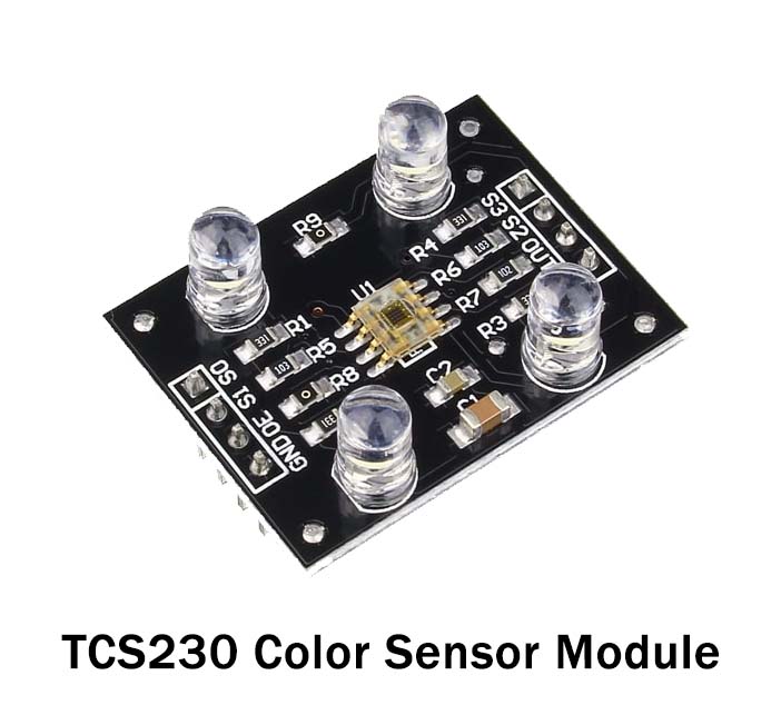
Specifications about TCS230/TCS3200
- The operation voltage range is from 3 to 5V
- It has a dimension of 3cm×2.7cm
- The sensor has four communication interface pins
- The sensor easily communicates to the microcontroller
Hardware Required
| S.no | Component | Value | Qty |
|---|---|---|---|
| 1. | Arduino | UNO | 1 |
| 2. | USB Cable Type A to B | – | 1 |
| 3. | Jumper Wires | – | 1 |
| 4. | Color Sensor | TCS230, TCS3200 | 1, 1 |
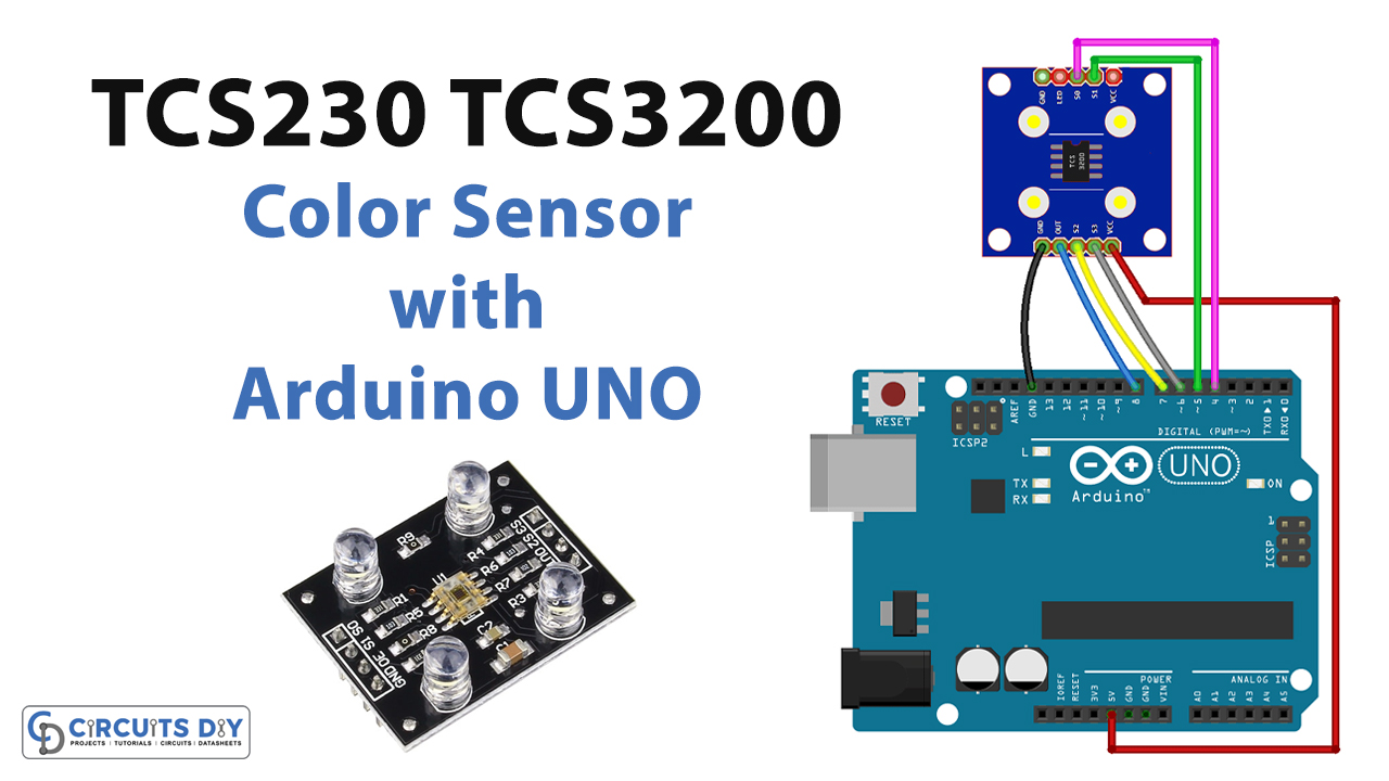
Circuit Diagram

Connection Table
| Arduino | TCS230/TCS3200 Color Sensor |
|---|---|
| D4 | S0 |
| D5 | S1 |
| 5V | VCC |
| D6 | S3 |
| D7 | S4 |
| D8 | OUT |
Arduino Code
// Circuits DIY
 // For Complete Details Visit -> https://circuits-diy.com
// TCS230 or TCS3200 pins wiring to Arduino
#define S0 4
#define S1 5
#define S2 6
#define S3 7
#define sensorOut 8

// Stores frequency read by the photodiodes
int redFrequency = 0;
int greenFrequency = 0;
int blueFrequency = 0;

void setup() {
  // Setting the outputs
  pinMode(S0, OUTPUT);
  pinMode(S1, OUTPUT);
  pinMode(S2, OUTPUT);
  pinMode(S3, OUTPUT);

  // Setting the sensorOut as an input
  pinMode(sensorOut, INPUT);

  // Setting frequency scaling to 20%
  digitalWrite(S0,HIGH);
  digitalWrite(S1,LOW);

   // Begins serial communication
  Serial.begin(9600);
}
void loop() {
  // Setting RED (R) filtered photodiodes to be read
  digitalWrite(S2,LOW);
  digitalWrite(S3,LOW);

  // Reading the output frequency
  redFrequency = pulseIn(sensorOut, LOW);

   // Printing the RED (R) value
  Serial.print("R = ");
  Serial.print(redFrequency);
  delay(100);

  // Setting GREEN (G) filtered photodiodes to be read
  digitalWrite(S2,HIGH);
  digitalWrite(S3,HIGH);

  // Reading the output frequency
  greenFrequency = pulseIn(sensorOut, LOW);

  // Printing the GREEN (G) value
  Serial.print(" G = ");
  Serial.print(greenFrequency);
  delay(100);

  // Setting BLUE (B) filtered photodiodes to be read
  digitalWrite(S2,LOW);
  digitalWrite(S3,HIGH);

  // Reading the output frequency
  blueFrequency = pulseIn(sensorOut, LOW);

  // Printing the BLUE (B) value
  Serial.print(" B = ");
  Serial.println(blueFrequency);
  delay(100);
}
Working Explanation
Connect the TCS230/TCS3200 Color Sensor with Arduino UNO. Upload the code in an Arduino UN0. Open the serial monitor. You will see the readings for red, blue, and green colors. Place the senor in blue color. The photodiodes in the sensor convert the light into current. And, you will see that the reading of blue will drop down. The same happens with the other two colors. And, that’s how you detect the color
Code Explanation
- Firstly, we have defined the connection pins of Arduino with the pins of the sensor. Then we have defined the variables that stores the frequency read by the photodiode
- In the void setup, we have declared the input and output pins. And, initialized the serial monitor.
- In the void loop, to set the red filtered photodiode we have defined two control pins, S3 and S4 at the low logic level. To set the green filtered photodiode, we have defined S2 and S3 as high levels. And, to set the blue filtered photodiode, we declared S2 at a high level and S3 at a low level
Application and Uses
It has applications in almost every industry including:
- Automation
- Printing
- Textile
- Medical
- Food, etc