Introduction
To detect the closeness or proximity of any particular object, a switch which is known as a proximity switch is employed. Basically, these switches are non-contact sensors. Generally, there are two types of proximity switches that are majorly utilized. Inductive proximity switch and capacitive proximity switch. Capacitive proximity switches detect the presence of non-metallic objects through the use of a high-frequency electric field. On the other hand, inductive proximity switches sense the proximity of the metallic object through the use of a high-frequency magnetic field. Hence, this article is mainly about the inductive proximity switch circuit and its explanation.
Hardware Required
| S.no | Component | Value | Qty |
|---|---|---|---|
| 1. | IC | TCA505BG | 1 |
| 2. | LED | – | 2 |
| 3. | Ceramic Capacitor | 0.1uF, 3.3pF | 3, 1 |
| 4. | Potentiometer | 10KΩ | 1 |
| 5. | Electrolytic Capacitor | 10uF | 1 |
| 6. | Resistors | 1K, 10K, 680 ohm | 1, 1, 3 |
| 7. | Inductor | – | 1 |
| 8. | 4 Pin Connector | – | 1 |
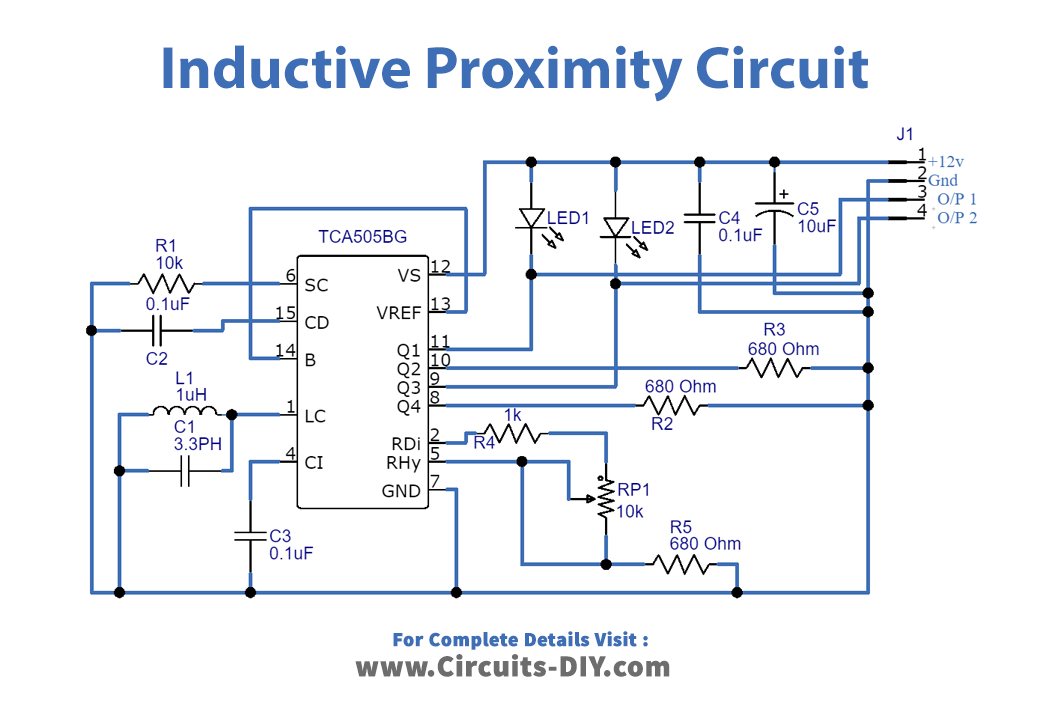
Circuit Diagram
Working Explanation
Inductive Proximity Switch Circuit has TCA505BG IC having 16 pins. Pin 12 is the supply voltage pin having a 12v supply there, pin 7 is the ground pin, and pin 6 is the short circuit detector pin. Pin 13 is the reference voltage pin that is connected with the base output transistor pin. RDI (pin2) manages is a distance pin and RHY (pin5) manages hysteresis. Pin 1 is the oscillator pin. There are 4 output pins, which are pins 8, 9, 10, and 11. Since we only needed two output pins, therefore, the other two pins are grounded. Now, the circuit would detect any close magnetic metal object.
Application and Uses
- To detect the near metallic objects.
- Any device that needs to check the proximity of a metal object having magnetic characteristics.