Introduction
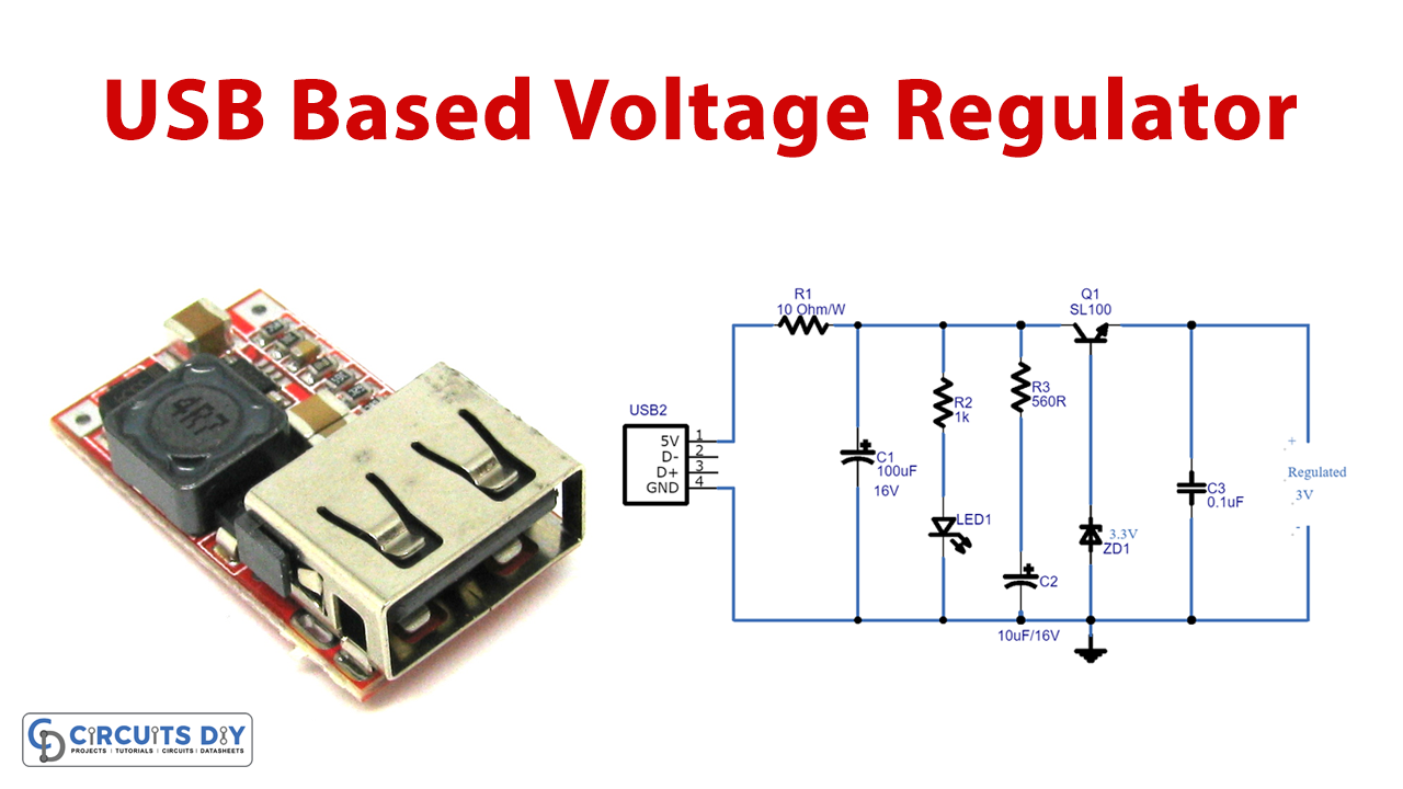
We know that voltage regulators offer controlled output voltage and are commonly employed in embedded systems when we talk about them. A regulated power supply, for example, ensures that the output does not vary when the input signals change. To put it another way, the outcome is consistent and independent of the input. In this tutorial, we are going to the “USB-based Zener diode regulator circuit”.
In the making of the circuit, we are employing a Zener diode. A Zener diode permits current to flow not just from the anode to the cathode, but also in the opposite direction when the Zener voltage is reached. Zener diodes are the most widely used semiconductor diodes because of their feature.
Hardware Components
The following components are required to make Zener Diode Voltage Regulator Circuit
| S.no | Component | Value | Qty |
|---|---|---|---|
| 1. | Transistor | SL100 | 1 |
| 2. | Zener Diode | 3.3v | 1 |
| 3. | LED | – | 1 |
| 4. | USB | – | 1 |
| 5. | Electrolyte Capacitor | 10uF, 100uF | 1, 1 |
| 6. | Ceramic Capacitor | 0.1uF | 1 |
| 7. | Resistor | 1KΩ, 10Ω, 560Ω | 1, 1, 1 |
| 8. | Battery | 3V | 1 |
| 9. | 2-Pin Connector | – | 1 |
SL100 Pinout
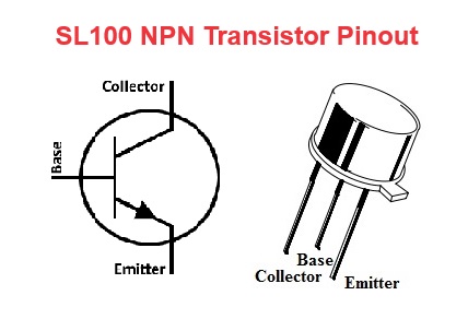
For a detailed description of pinout, dimension features, and specifications download the datasheet of SL100
Zener Diode Voltage Regulator Circuit
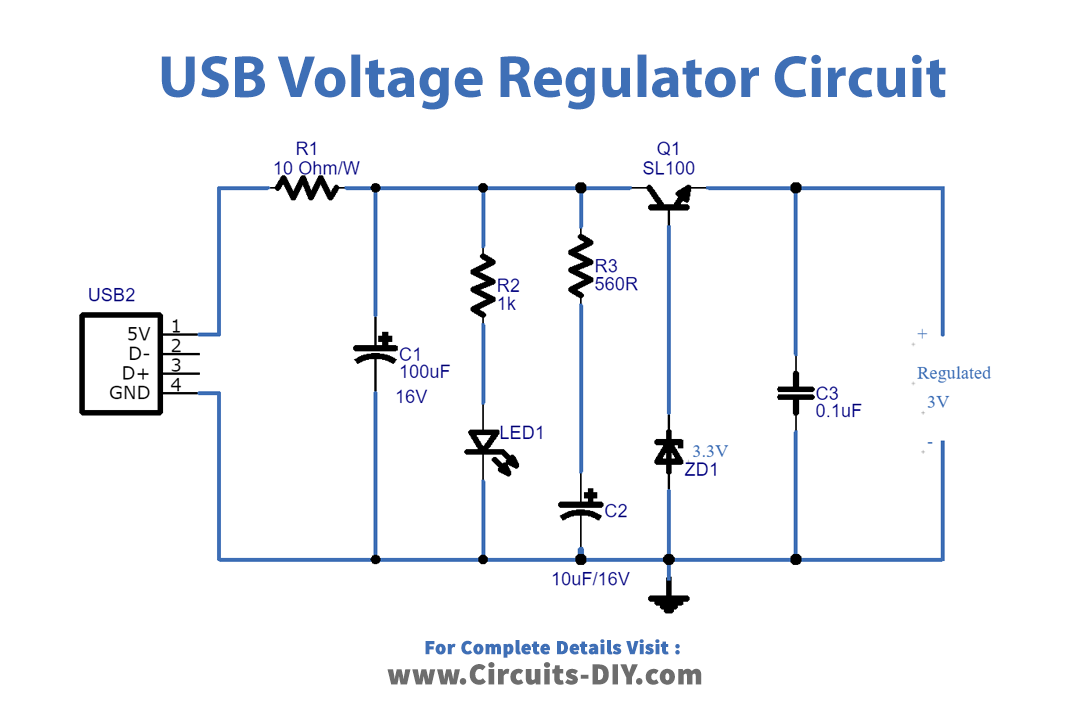
Working Explanation
The USB port provides DC bias of the power supply, which is regulated by a Zener diode. We can acquire varied levels of controlled DC voltage by using different voltage Zener diodes. When using a USB power supply, we can use a Zener diode with a maximum voltage of 5V. The power supply is shown by the LED linked to the R2 resistor, the output supply is driven by the transistor SL100, and the USB port is protected by the resistor R1.
Application and Uses
- Voltage regulators can be used to power sensors, operational amplifiers, and other electronic components and devices that require both regulated voltages.