Introduction
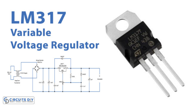
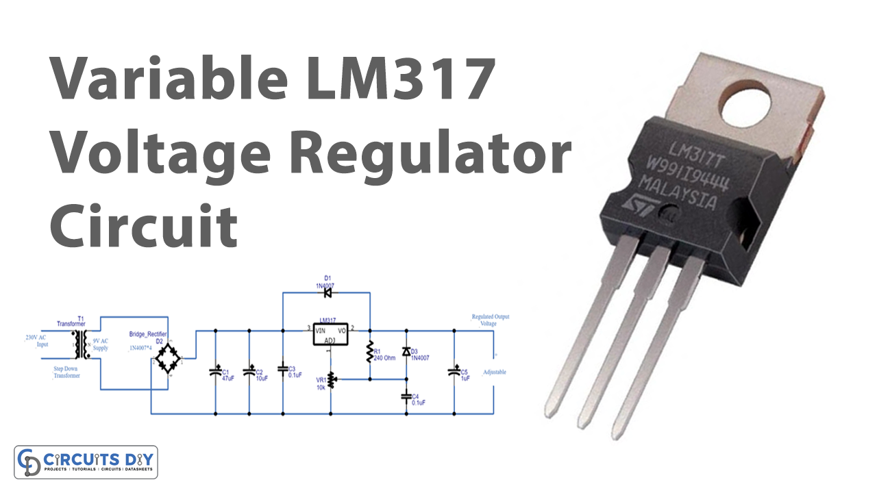
When we address the voltage regulator, we know that they provide regulated output voltage, usually used in embedded systems. Primarily, a regulated power supply enables the output not to make any changes if the changes would be made in input signals. In simpler words, you can say that the output is stable and is independent of the input. Now coming towards the variable voltage regulator, these are the circuits that allow to vary or change the output voltage within the defined range. To understand this circuit, in this tutorial, we are going to make a “Variable LM317 voltage regulator circuit”. To make this circuit our main component is the adjustable voltage regulator IC LM317 having an output voltage range from 1.2V to 37V.
Hardware Required
| S.no | Component | Value | Qty |
|---|---|---|---|
| 1. | Transformer | 0-9V 1 amp | 1 |
| 2. | Diode | 1N4007 | 6 |
| 3. | Voltage Regulator IC | LM317 | 1 |
| 4. | Potentiometer | 10K | 1 |
| 5. | 2 Pin Connector | – | 2 |
| 6. | Capacitor | 47uF, 10uF, 1uF, 0.1uF | 1, 1, 1, 2 |
| 7. | Resistor | 240Ω | 1 |
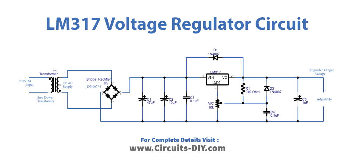
Circuit Diagram
Working Explanation
This Variable LM317 voltage regulator uses the first stage of the transformer where it steps down the voltage to 25 V. After that, the rectifier circuit that is made from diodes converts. It converts both input polarities into pulsating DC. But, it still has ripples in it which get filtered by the capacitors C1, C2, and C3 wired in the circuit. The output is given to the input pin of IC. This IC has an ADJ pin where we connected the potentiometer. This potentiometer is used to vary the output voltage from 1 to 30 V. Hence, the output is taken across the capacitor C5. Diode D2 provides reverse voltage protection.
Application and Uses
- Different electronic devices use this circuit.
- Power supply circuit.