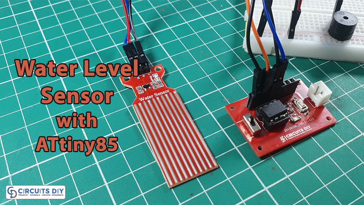
Introduction
A water level indicator, as the name implies, is a system that signals specific levels of water or other liquid, and it is used in a variety of applications. It may be used to measure the water level in the tank of a boiler in industries, and it can also be used to check the amount of water that crops require in agriculture. In conclusion, we may adopt this fundamental circuit in several situations. The level of water is detected via water level sensors. in those circuits. Industry, chemical plants, and other liquid storage systems all use water level sensors. So, in this tutorial, we are going to make Water Level Sensor with ATtiny85 and Buzzer Indicator.
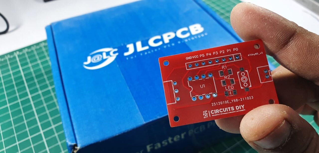
JLCPCB is the foremost PCB prototype & manufacturing company in china, providing us with the best service we have ever experienced regarding (Quality, Price Service & Time).
Hardware Overview of Water Level Sensor
There are ten exposed copper traces on the sensor, five of them are power traces and five are sensing traces. These traces are linked so that per two power traces there is one sensory trace. When submerged, these traces are usually not linked but are bridged by water.
Technical Specifications of Sensor
- Operating voltage: DC: 3-5V
- Operating current: less than 20mA
- Sensor Type: Analog
- Detection Area: 40mmx16mm
- Operating temperature: 10℃-30℃
- Humidity: 10% -90% non-condensing
Hardware Required
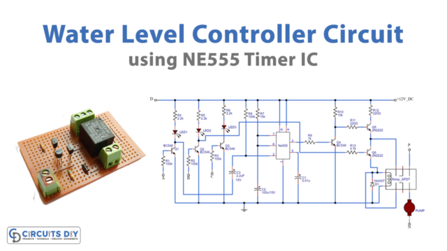
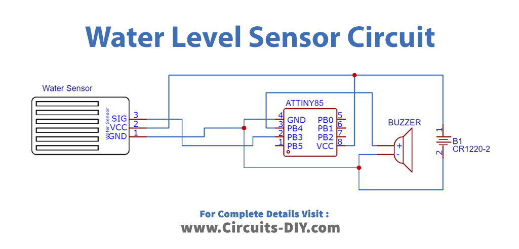
Circuit Diagram
Arduino Code
#define sensorPin A3
#define buzzer 4
// Value for storing water level
int val = 0;

void setup() {
pinMode(buzzer, OUTPUT);
digitalWrite(buzzer,LOW);
}

void loop() {

  int level = analogRead(sensorPin);
  if(level>450)
  {
  digitalWrite(buzzer,HIGH);
  }
  else
  {
  digitalWrite(buzzer,LOW);
  }
  delay(1000);
}
Working Explanation
In this Water Level Sensor with ATtiny85, by following the schematic and uploading the above-mentioned code to your controller IC when the module detects readings that are higher than the set threshold, it will send them to the controller. As a result, the buzzer starts to beep.
The resistance and the levels of water are inversely proportional to each other. at higher levels of water, the conductivity of the sensor gets high. Hence, the resistance gets low. In the same vein, at the lower levels, the conductivity is low. And the resistance is higher. According to this resistance, the sensor estimates the voltage, which then helps to measure the water level.
Code Explanation
- First, define the controller pin that is connected with the water level sensor. Also, define the controller pin which is connected to the buzzer. After that define the variable val stores the integer water level.
- In the void setup, declare the buzzer as output by using the pinMode function. Also, for the initial state, set the buzzer value low using the digitalWrite( ) function.
- In the void loop, define the variable level that stores the integer readings coming from the sensor. To get the readings use the function analogRead. Then give the if condition. If the reading is greater than the defined threshold reading, which in our case is 450, the buzzer value would get high, which means the buzzer will beep; otherwise, it will remain low. At last, give some delay to get the other reading
Application and Uses
- Devices for home automation.
- For the regulation of oil tanks.
- Control systems for irrigation.
- Controlling the level of a gasoline tank, etc