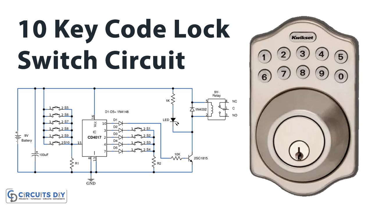
In this tutorial, we are going to make a “10 Key Code Lock Switch Circuit”.
This code lock switch is an electronic circuit, to replace a conventional key switch. We do not need to carry a load key and do not worry about the keys being lost. Because of this circuit, you only need to press the number code instead of unlocking keys. But we just must remember the code. It is a simple digital circuit without a microcontroller. Thus, there is no programming, easy to use, and is cheaper.
Hardware Components
The following components are required to make Code Lock Switch Circuit
| S.no | Component | Value | Qty |
|---|---|---|---|
| 1. | IC | CD4017 | 1 |
| 2. | Transistor | 2SC1815 | 1 |
| 3. | Relay | 9V | 1 |
| 4. | Electrolytic Capacitor | 100uF | 1 |
| 5. | Resistor | 1K,100K,10K | 1 |
| 6. | Diodes | 1N4148,1N4002 | 5,1 |
| 7. | LED any color | 3mm | 1 |
| 8. | Switch | – | 10 |
| 9. | PCB | – | 1 |
CD4017 Pinout
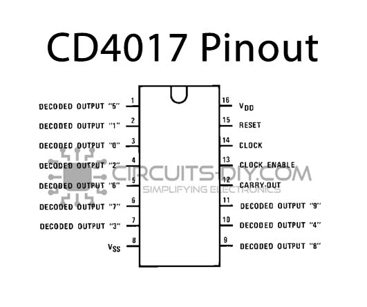
For a detailed description of pinout, dimension features, and specifications download the datasheet of CD4017
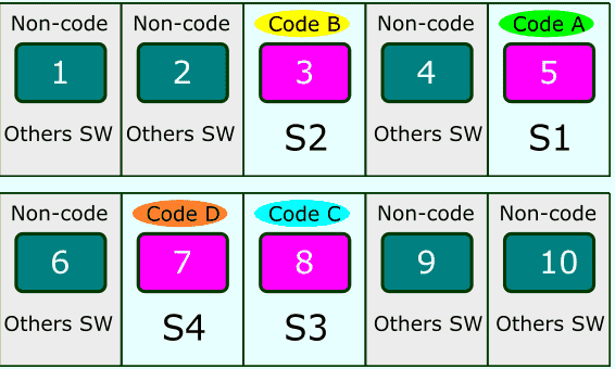
When we need any code, can connect the code number to switch positions. The order of the codes is not necessarily in the order of switches. For example, we need code is 4675. We have to connect as follows.
- First, CODE 4 to Switch 1 (A) at pin 3 of IC1
- Second, CODE 6 to Switch 2 (B) at pin 2 of IC1
- Third, CODE 7 to Switch 3 (C) at pin 4 of IC1
- Fourth, CODE 5 to Switch 4 (D) at pin 7 of IC1
- Fifth, other CODEs to Switch 5 to 10, to connect to pins of IC1
Look at the code diagram below.
Code Lock Switch Circuit

Working Explanation
In This circuit, we have a 74HC4017 or CD4017 IC. It is a decode counter model, that serves to change the code. First, when we powered this circuit, there is a positive voltage at the output PIN3 of IC1. As you press S1 of switch A, the positive voltage from PIN3 goes to the input pin (PIN14) of IC1. Now, when IC1 has input a positive voltage, it will move the output from PIN3 to PIN2. So, the next switch that we must press is switch B of S2. Which causes the positive voltage at the input of IC1, in the next step. If we do not press switch B, it will not make any change in IC1. And if we push a wrong switch from one of six options on the left-hand side of this circuit. It will pass the positive voltage through this switch to the input PIN15, which is the reset pin of IC1. So IC1 will transfer the output positive voltage from PIN15 to PIN3. This resets switch A to start again.
If we press these switches in the correct order from A, B, C, and D, IC1 will move output to PIN10. It is connected with pin B of Q1-2SC1815 through a diode and R-10K. Then, Q1 conducts power to relay-RY1 and LED1, they are working together. the LED will light up. Relay-RY1 acts like SPDT switches (Single-Pole, Double-throw). We normally press this switch, right? But now we are feeding the current coil of the relay. It will become electromagnetic, and sucking or plugging the switch contacts instead of our fingers. So, it can control other loads. The 5 diodes that are connected to the out of IC1, protect a collision of the output. For example, the two same-digit in the code are 5385.
Applications
This circuit can be used in homes, malls, offices, and banks.
Related posts:
 How To Make An Remote Control RC Motor Driver Using CD4017 IC - DIY
 Crowbar Overvoltage Protection Circuit
 Sound Activated Adjustable Battery Supply Using ICM7555 Timer
 TCA505BG Inductive Proximity Switch Circuit
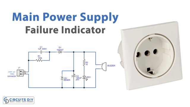 Main Power Supply Failure Indicator Circuit
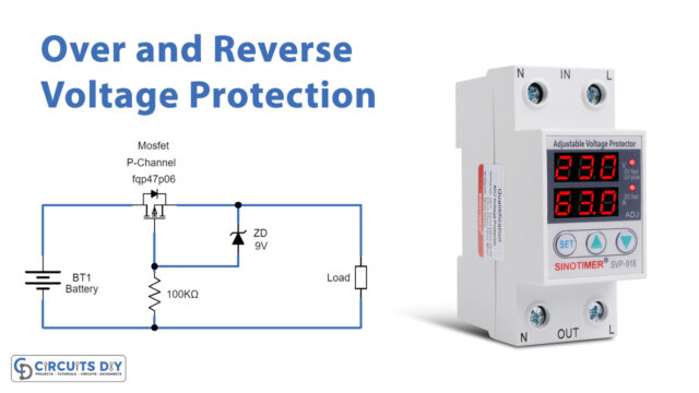 Over Voltage and Reverse Voltage Protection Circuit


