Introduction
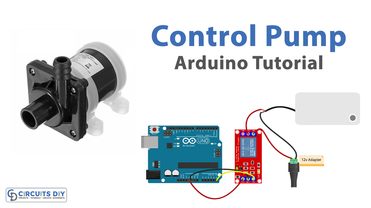
Controlling a 12 Volt DC Diaphragm Pump with a 5V SPDT relay using an Arduino UNO microcontroller involves using the Arduino board to control the state of the relay, which in turn controls the state of the pump. The Arduino board is connected to the relay through a digital pin, and the relay is connected to the pump. By sending a digital signal to the relay, the Arduino board can turn the pump on or off. The relay acts as an electronic switch, which can be controlled by the Arduino board’s digital output to control the power to the pump.
A 12V DC diaphragm pump is a type of positive displacement pump that is used to move fluids, such as water, through a system. The pump is powered by a DC voltage, typically 12V, and has a flexible diaphragm that moves back and forth to pump the fluid. The diaphragm is actuated by a motor or other mechanical means.
Hardware Components
You will require the following hardware for 12V Water Pump Control with Arduino.
| S.no | Component | Value | Qty |
|---|---|---|---|
| 1. | Arduino UNO | – | 1 |
| 2. | USB Cable Type A to B | – | 1 |
| 3. | Relay | – | 1 |
| 4. | Pump | 12V | 1 |
| 5. | Vinyl Tube | – | 1 |
| 6. | Power Adapter | 12V | 1 |
| 7. | DC Power Jack | – | 1 |
| 8. | Power Adapter for Arduino | 9V | 1 |
| 9. | Jumper Wires | – | 1 |
Control Pump with Arduino
- Include the necessary libraries: The first step is to include the necessary libraries in the code. In this case, you will need to include the Arduino library.
#include <Arduino.h>
- Define the pin numbers: Define the pin numbers of the relay as constants, for example:
const int relayPin = 3;
- Initialize the relay in the setup function: In the setup function, use the pinMode() function to set the relay pin as an output.
void setup() {
   pinMode(relayPin, OUTPUT);
   Serial.begin(9600);
}
- Control the relay in the loop function: In the loop function, use the digitalWrite() function to control the state of the relay and thus control the state of the pump.
void loop() {
  digitalWrite(relayPin, HIGH); // turn on pump 5 seconds  delay(5000);
  digitalWrite(relayPin, LOW);  // turn off pump 5 seconds  delay(5000);}
Schematic
Make connections according to the circuit diagram given below.
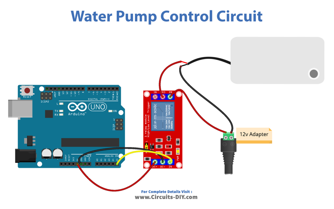
Wiring / Connections
| Arduino | Relay |
|---|---|
| 5V | VCC |
| GND | GND |
| A5 | INP |
Installing Arduino IDE
First, you need to install Arduino IDE Software from its official website Arduino. Here is a simple step-by-step guide on “How to install Arduino IDE“.
Code
Now copy the following code and upload it to Arduino IDE Software.
const int RELAY_PIN = A5;  // the Arduino pin, which connects to the IN pin of relay

// the setup function runs once when you press reset or power the board
void setup() {
  // initialize digital pin A5 as an output.
  pinMode(RELAY_PIN, OUTPUT);
}

// the loop function runs over and over again forever
void loop() {
  digitalWrite(RELAY_PIN, HIGH); // turn on pump 5 seconds
  delay(5000);
  digitalWrite(RELAY_PIN, LOW);  // turn off pump 5 seconds
  delay(5000);
}
Working Explanation
In the setup() function, the first thing that is done is to initialize the serial communication by calling the Serial.begin() function. This allows the Arduino to send data to the serial monitor for monitoring and debugging purposes. Then, the pin mode of the digital pin connected to the relay is set as an output using the pinMode() function. This allows the Arduino to send a digital signal to the relay to turn it on or off.
In the loop() function, the first thing that is done is to read the state of the relay from the digital pin connected to it. This is done using the digitalRead() function. Depending on the state of the relay, the pump is turned on or off by sending a digital signal to the relay using the digitalWrite() function. After that, the state of the relay and the pump is sent to the serial monitor using the Serial.println() function. This allows the user to monitor the state of the relay and the pump in real-time.
Applications
- Irrigation systems
- Rainwater harvesting systems
- Chemical transfer
- Mobile applications
- Laboratory
- Medical devices
- Aquariums
- Water treatment systems
- Pool and spa systems
- Beverage dispensing systems
Conclusion.
We hope you have found this Arduino – Control Pump Circuit very useful. If you feel any difficulty in making it feel free to ask anything in the comment section.