Introduction
If you are a person who enjoys playing video games, then you have probably heard of joysticks by this point. But that’s not the only use for it. You could also see it in both modern and old-fashioned vehicles. In light of this, it is clear that the present world also extensively uses it. Incredibly, a joystick can interpret even the slightest of finger movements.
If you like building your own devices, there are several fun projects you can do with joysticks. So, what do you think of connecting a joystick to an Arduino? Fascinating idea? So, let’s plunge in!
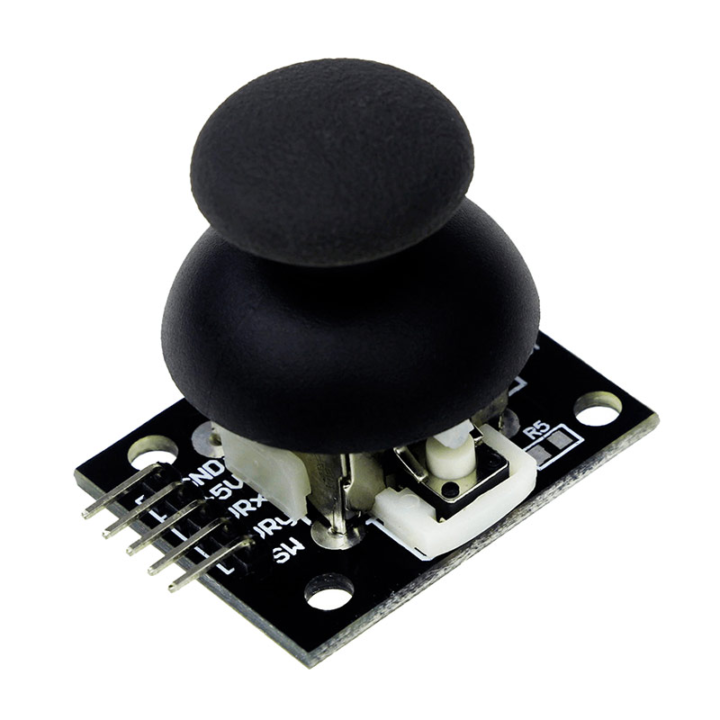
What is a 2-Axis Joystick?
Joysticks with two axes are devices that allow users to move a machine in two dimensions (i.e., forward and backward, as well as left and right). A joystick’s primary function is to provide a microcontroller with an electrical signal corresponding to the stick’s location along two axes: the X-axis, left to right, and the Y-axis, up and down.
Hardware Components
You will require the following hardware.
| S.no | Components | Value | Qty |
|---|---|---|---|
| 1 | Arduino | UNO | 1 |
| 2 | 2-Axis Joystick | KY-023 | 1 |
| 3 | Breadboard | – | 1 |
| 4 | Jumper Wires | – | 1 |
Steps Interface Joystick with Arduino
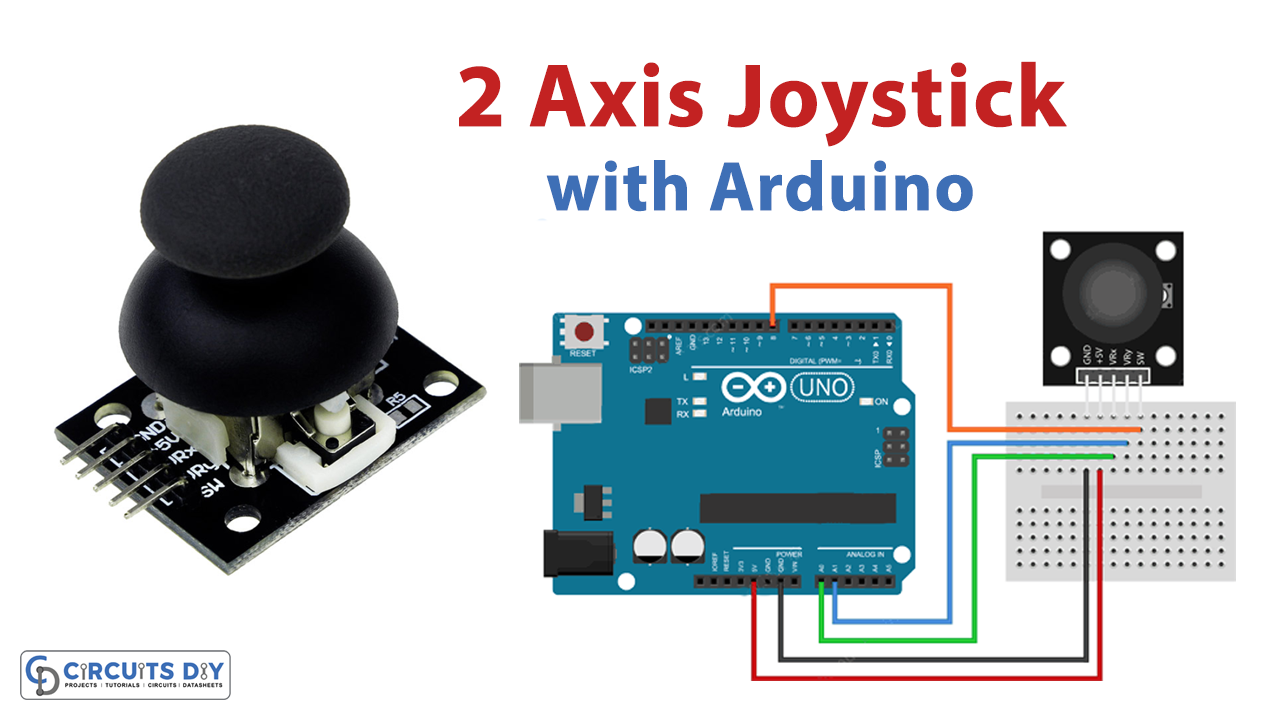
Schematic
Make connections according to the circuit diagram given below.
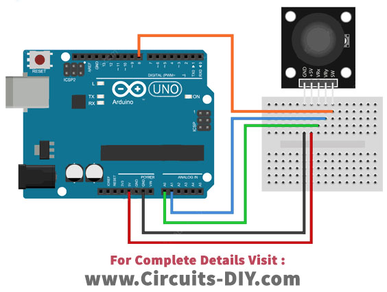
Wiring / Connections
| Arduino | 2-Axis Joystick |
|---|---|
| GND | GND |
| 5V | VCC |
| A0 | VRX |
| A1 | VRY |
| D8 | SW |
Installing Arduino IDE
First, you need to install Arduino IDE Software from its official website Arduino. Here is a simple step-by-step guide on “How to install Arduino IDE“.
Code
Now copy the following code and upload it to Arduino IDE Software.
// Arduino pin numbers
const int SW_pin = 8; // digital pin connected to switch output
const int X_pin = 0; // analog pin connected to X output
const int Y_pin = 1; // analog pin connected to Y output

void setup() {
  pinMode(SW_pin, INPUT);
  digitalWrite(SW_pin, HIGH);
  Serial.begin(9600);
}

void loop() {
  Serial.print("Switch:  ");
  Serial.print(digitalRead(SW_pin));
  Serial.print(" | ");
  Serial.print("X-axis: ");
  Serial.print(analogRead(X_pin));
  Serial.print(" | ");
  Serial.print("Y-axis: ");
  Serial.print(analogRead(Y_pin));
  Serial.println(" | ");
  delay(200);
}
Let’s Test It
It’s now time to test the circuit. After you’ve finished wiring, open the serial monitor and look at the readings that look like this:

Working Explanation
To understand the working of the circuit, you first need to understand the code.
- In the code, we first define the pins connected to the Arduino. If you see the circuit diagram, you can see that we have utilized three pins of Arduino (analog and one digital) to connect the sensor. So, name those pins, and we define them as constant integers to save their values.
- In void setup, we declared the SW pin of the module as input since it takes values from these pins. We also make that pin high. After that, we initialize the serial monitor.
- In the void loop, we took the digital readings from the SW pin using digitalRead. We also print that reading on the serial monitor. To take the two axes analog readings, we have used the analogRead function. We also print those values. To print the values, we have used serial.Print function. Then, we give a little delay to get a new reading.
This code gives the computer, push button, and analog outputs a serial connection. The corresponding Processing code can read serial data and display it on a serial monitor.
Applications
- Agricultural machines
- Forestry machines
- Construction Equipment
- Material handling vehicles
- Robotic arms
- Medical devices
- Gaming devices, etc.
Conclusion
We hope you have found this Circuit very useful. If you feel any difficulty in making it feel free to ask anything in the comment section.