Introduction
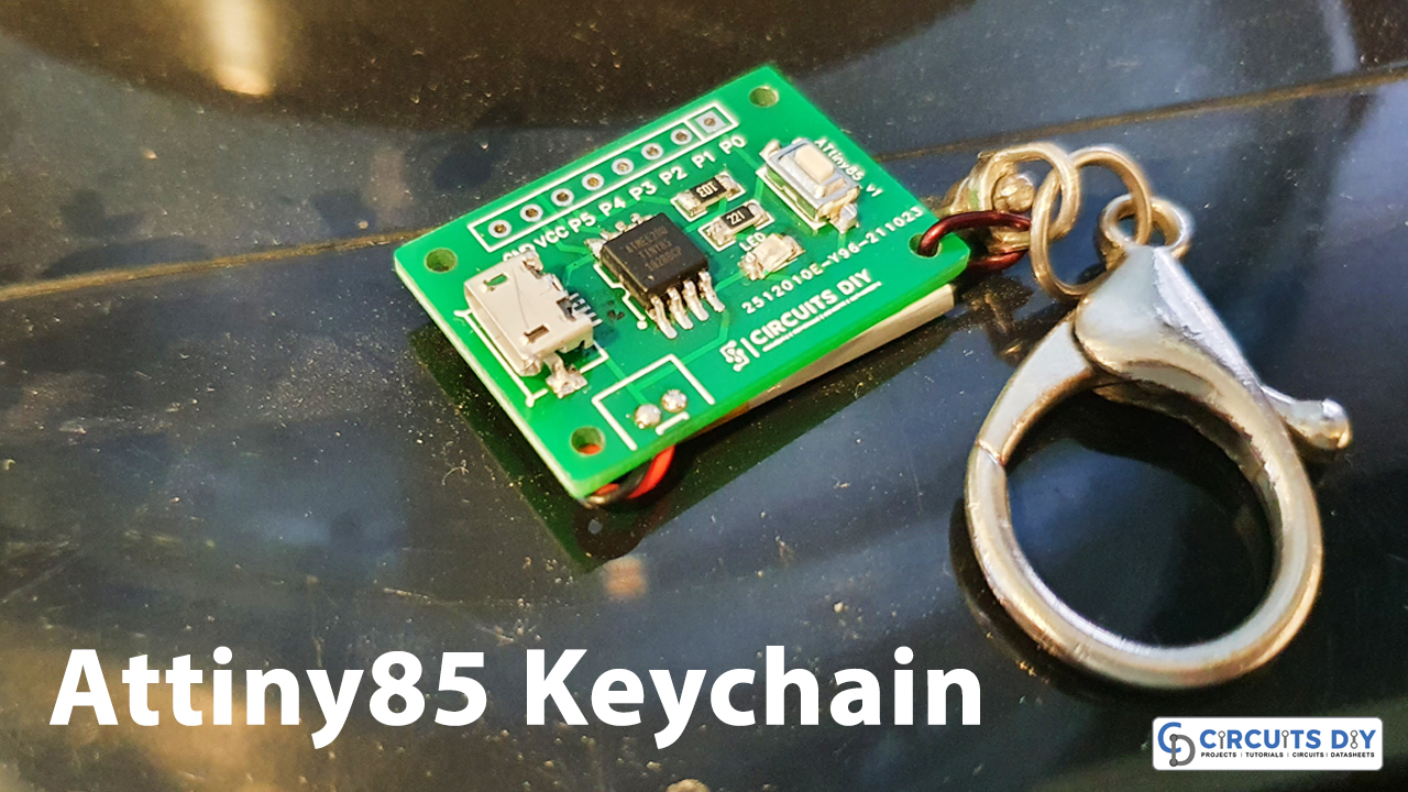
We all buy key chains and many of us have a crazy fascination with them to buy. Thus, there are different kinds of key chains available in the market for children and adults. Many keychain brands launch keychain that represents different passions that people are involved in. For example, a person who loves cartoons would like to have his favorite cartoon keychain, those who love books would like to have a related keychain. Thus, it depends on obsessions or passions. So, today we are making the keychain for electronic learners. Those who are fond of microcontrollers, those who find electronics their joy. So, in this tutorial, we are going to make a simple “Keychain based on Attiny85 Microcontroller”. Watch this step-by-step video below for complete details.
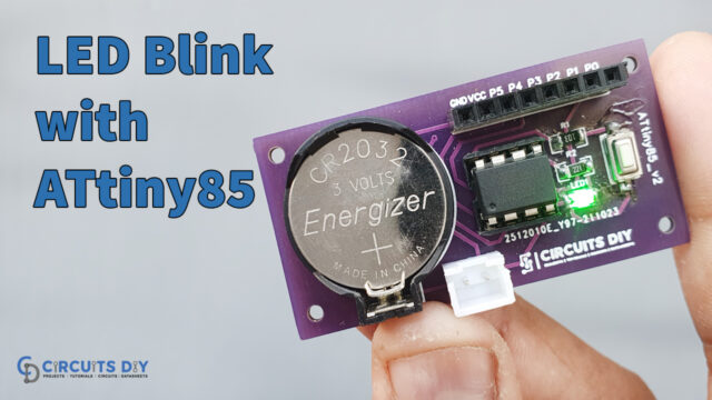
Now, to make this blinking Attiny85 keychain board, we are using Attiny85 as our main component. The ATtiny85 microcontroller is a low-cost integrated circuit with a lot of power. The microcontroller has an 8-Bit data bus, which implies that each command can access 8 bits of data. It has an 8KB flash memory for storing programs and a CPU speed of up to 8MHz. It contains 5 Input/Output pins for interfacing electronic components and requires an operating voltage of 1.8V to 5.5V.
PCBWay commits to meeting the needs of its customers from different industries in terms of quality, delivery, cost-effectiveness, and any other demanding requests. As one of the most experienced PCB manufacturers in China. They pride themselves to be your best business partners as well as good friends in every aspect of your PCB needs.
Hardware Components
The following components are required to make ATtiny85 Keychain Circuit
| S.no | Component | Value | Qty |
|---|---|---|---|
| 1. | Attiny85 | – | 1 |
| 2. | PCB | – | 1 |
| 3. | SMD Resistor | 10K, 330 | 1, 1 |
| 4. | Micro USB connector | – | 1 |
| 5. | Lithium Battery | – | 1 |
| 6. | SMD LED | – | 1 |
| 7. | Push Button | – | 1 |
ATtiny85 Pinout
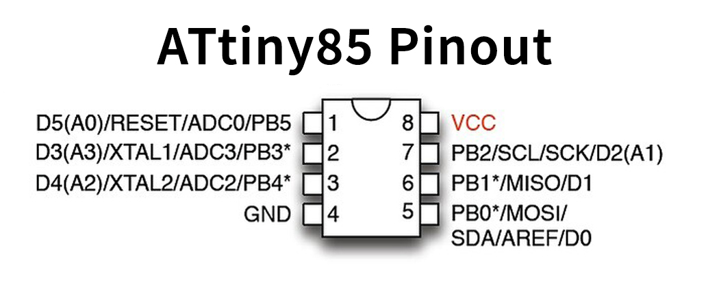
For a detailed description of pinout, dimension features, and specifications download the datasheet of ATtiny85
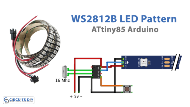
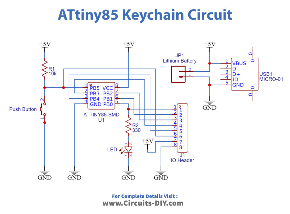
ATtiny85 Keychain Circuit
Arduino Code
void setup() {
  // put your setup code here, to run once:
pinMode(0,OUTPUT);
pinMode(1,OUTPUT);
pinMode(2,OUTPUT);
 digitalWrite(0,1);
  digitalWrite(1,1);
   digitalWrite(2,1);
   delay(1400);
   digitalWrite(0,0);
  digitalWrite(1,0);
   digitalWrite(2,0);
   delay(600);
}
int mod=5;
int pritisnuto=0;
void loop() {

for(int i=0;i<3;i++)
  {
    if(digitalRead(3)==0)
    {
      if(pritisnuto==0)
      {
        pritisnuto=1;
        mod=mod-1;
        if(mod==0)
        mod=5;
        }
      }else{ pritisnuto=0;}
    digitalWrite(i,1);
    delay((mod*80)-50);
    digitalWrite(i,0);
  }

}
Working Explanation
To make the Attiny85-based Keychain Board first you need to make and solder a circuit according to the diagram given, then upload the code. When you upload the code, provide the supply, and click the button, the three LEDs begin to blink one after another. If we press the button again, the blinking will become faster.
Code Explanation
- In the void setup, define the pins that are connected as output. Then by using the function digitalWrite declared all of them as 1, which means high. Then after some delay uses the same function to set those pins low.
- In the void loop, we have given the if function for LED blinking.
Application and Uses
This board can be used as a keychain by electronics enthusiasts and learners.