Introduction
If you own a classic car with a positive earth body, then you know the challenges of maintaining its electrical system. That’s why we’re excited to share a new, improved battery charger circuit concept that can help improve your car’s performance.
This 6V and 12V battery charger circuit, comprising of an LM396 adjustable voltage regulator stage and a 555 IC-based 6V to 12V boost converter stage, is designed to work with an external 12V battery in addition to the current 6V battery, making it easier and more convenient to keep your car running smoothly. So, whether you’re a classic car enthusiast or simply looking for a reliable battery charger for your positive earth car, read on to learn more about this innovative circuit design.
Hardware Required
| S no | Components | Value | Qty |
|---|---|---|---|
| 1 | Voltage Regulator | LM396 | 1 |
| 2 | Transistor | BC547 | 1 |
| 3 | IC | NE555 | 1 |
| 4 | MOSFET | IRF540 | 1 |
| 5 | Resistor | 240R, 100R, R1 = 10K R2, R5 = 1k R3 = 33K R4 = 220K R6 = 100K | 1, 1 1 2 1 1 1 |
| 6 | Capacitor | C1 = 1nF C2 = 100uF/25V C3 = 0.1uF C4 = 1uF/400v | 1 |
| 7 | Diode | 10amp D1 To D5 = 6A4 | 2 5 |
| 8 | Battery | 6V 12V | 1 1 |
| 9 | V. Resistor | 10k | 1 |
Circuit Diagram
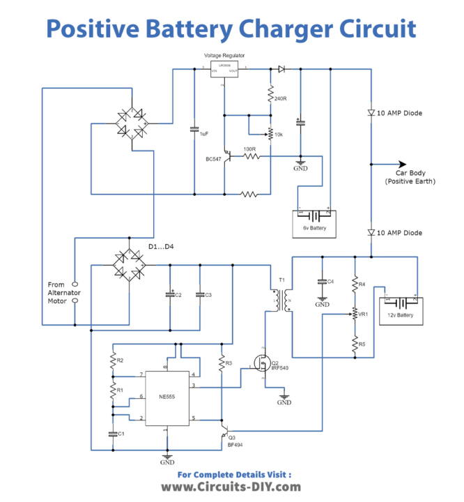
T1 BF494
Q1 IRF540
D1-D5-6A4
IC 1 555
Working Explanation
The battery charger circuit for positive earth cars consists of two main stages: the LM396 adjustable voltage regulator stage and the 555 IC-based 6V to 12V boost converter stage.
The LM396 stage is responsible for generating a variable output range of 1.25V to the maximum voltage capacity of the alternator supply. This voltage range is determined by the setting of the 10K preset resistor, which can be adjusted to produce a constant output of 7V for the connected 6V battery.
To limit the current flowing through the circuit and prevent overcharging of the battery, a current limiter resistor is connected between the base and emitter of the BC547 transistor. The formula R determines the value of this resistor = 0.6 x 10/Battery AH, where AH stands for Ampere-hour, a unit of electric charge used to measure battery capacity.
The 555 IC-based boost converter stage is responsible for stepping up the 7V AC voltage from the alternator to the required 14V for charging an optional 12V battery. This stage uses a coil (TR1) and a preset VR1 to fine-tune the output voltage to 14V across the battery.
The coil (TR1) is wound using a 1-inch OD core and 1mm magnet wire. It comprises of a primary winding with 12 turns and a secondary winding with 24 turns of 1mm magnet wire.
Together, these two stages work in tandem to provide a reliable and efficient battery charging solution for positive earth cars. By using an external 12V battery in addition to the current 6V battery, this circuit design makes it easier to maintain and improve the performance of your classic car’s electrical system.
Final Words
We hope you found our battery charger circuit for positive Earth cars informative and valuable. This circuit is designed to help improve the performance of classic vehicles with positive earth bodies and make it easier to maintain their electrical systems. The LM396 adjustable voltage regulator stage and 555 IC-based 6V to 12V boost converter stage work together to provide a reliable and efficient charging solution for both the 6V and optional 12V batteries.
If you have any questions or comments about this circuit design, please share them with us in the comments section. We always appreciate feedback and are happy to help with any queries you may have.
This circuit design can benefit classic car enthusiasts and anyone looking for a reliable battery charger for their positive earth car. Thank you for reading, and we look forward to hearing from you!