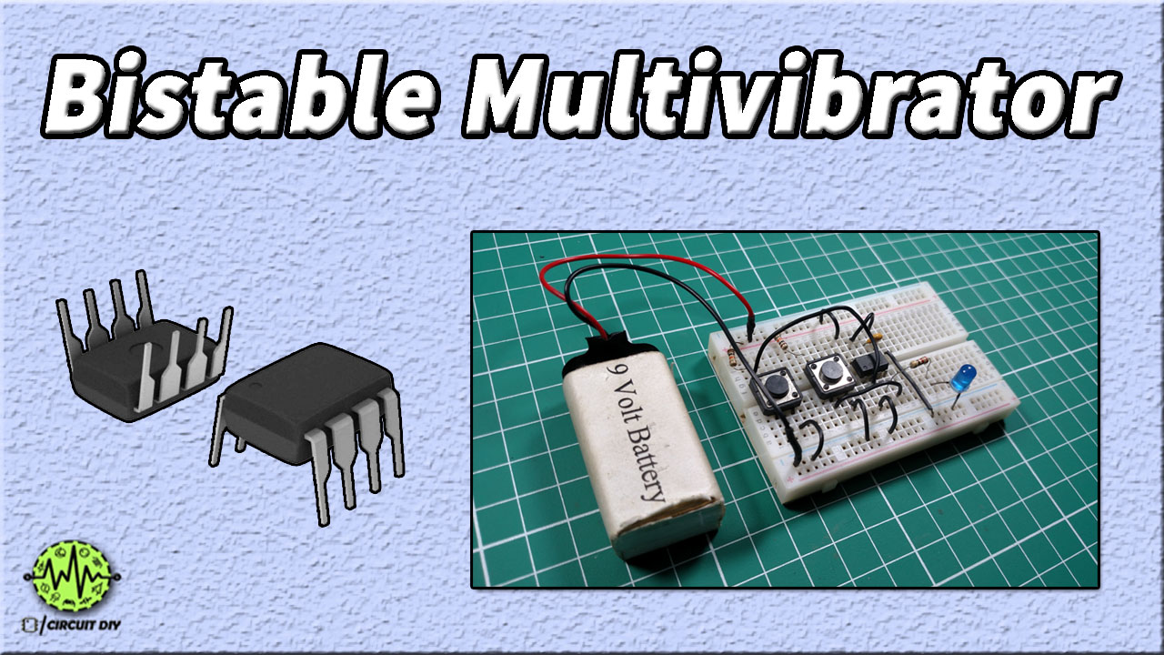
In this tutorial, we will show you how to make a Bistable Multivibrator circuit using 555 Timer IC. A bistable multivibrator has two stable states and it remains in the same state until and unless we apply an external trigger to the circuit. We also call these circuits flip-flops and latches. There is no RC timing network in a bistable circuit, so in order to control pulse width, we use an external trigger.

Hardware Required
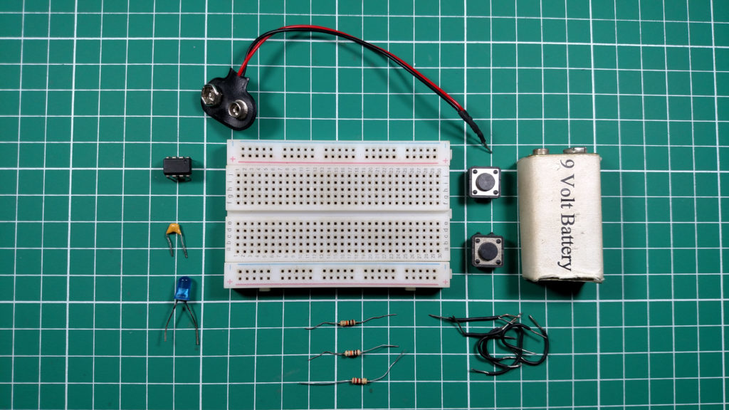
The following components are required to make Bistable Multivibrator Circuit
| S. NO | Component | Value | Qty |
|---|---|---|---|
| 1. | Breadboard | – | 1 |
| 2. | Battery | 9v | 1 |
| 3. | Connecting Wires | – | 1 |
| 4. | IC | NE555 Timer | 1 |
| 5. | Resistors | 10k, 220 ohm | 2, 1 |
| 6. | Ceramic Capacitor | 0.01uF | 1 |
| 7. | Push Button | – | 2 |
| 8. | LED | 5mm | 1 |
555 IC Pinout

For a detailed description of pinout, dimension features, and specifications download the datasheet of 555 Timer
Circuit Diagram
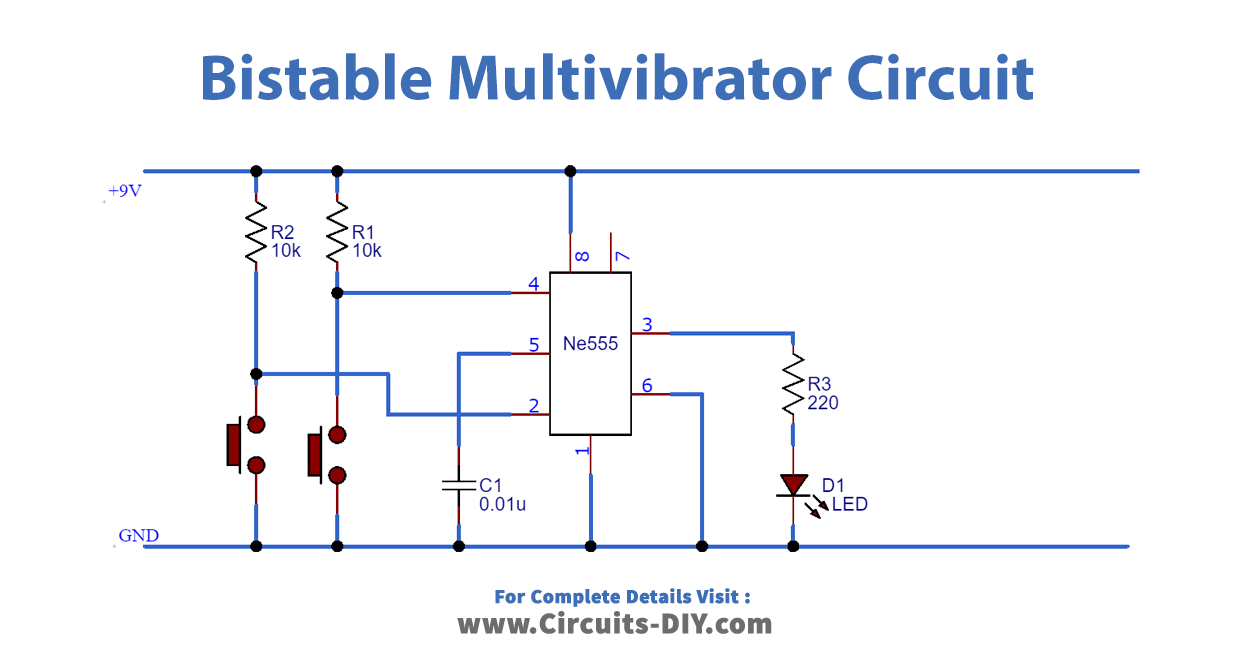
Connection
- Make power connections by connecting Pin 8 to VCC & Pin 1 to GND.
- Connect 0.01uF Capacitor at Pin 5.
- Use a jumper wire to connect Pin 6 to GND.
- Add a Push-button with a 10K Ω Resistor at Pin 4.
- Add another Push-button with a 10K Ω Resistor at Pin 2.
- Connect LED with 220 Ω Resistor at the output Pin 3.
Working Explanation
In this circuit, we have connected two switches at Pin numbers 2 & 4 in order to SET and RESET the output of the 555 timer. Resistors R1 & R2 are the pull-up resistors for these switches. When the switches are open Pin 2 & 4 will be in the High state and when the switches are closed, these Pins will go to a Low state. If we want to output at Pin 3 to be High, we will only close the switch connected to Pin 2 while the switch connected with Pin 4 will remain open.
Resistor R3 is connected in series with the LED at the output Pin 3. It acts as a current limiting resistor for the LED. Capacitor C1 is connected to Pin 5 of the 555 timer in order to avoid high-frequency noises.
Application
- They are used in circuits like Latches, Flip-flops, Frequency dividers and Counters.
- They are also used in digital communications.