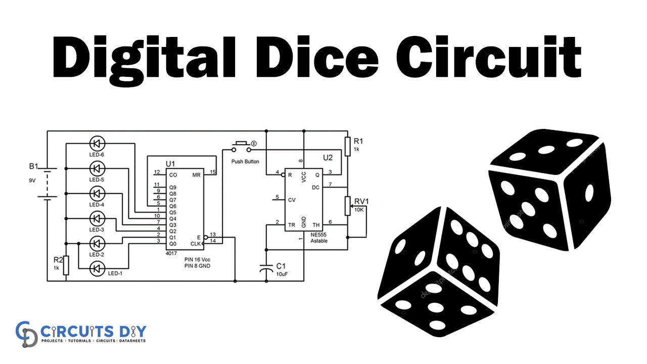
In this tutorial, we are going to develop a project of a Digital Dice Circuit. This circuit is easy to create and requires a few components. Dice is utilized to play numerous games like Ludo, snake ladder, and so forth. These dice are wooden or plastic, which gets distorted with time.
A Digital dice is a decent option for antiquated dice. It can’t be biased or distorted. It works so fast that nobody can cheat. To make this digital dice circuit, we have essentially utilized the 555 timer IC and IC 4017.
Hardware Components
The hardware components required to make this circuit are:
| S.no | Component | Value | Qty |
|---|---|---|---|
| 1. | IC | CD4017 | 1 |
| 2. | IC | NE555 timer | 1 |
| 3. | Resistor | 1k | 2 |
| 4. | Capacitor | 10uF | 1 |
| 5. | Variable Resistor | 10K | 1 |
| 6. | Push Button | – | 1 |
| 7. | LEDs | – | 1 |
| 8. | Battery | 9V | 1 |
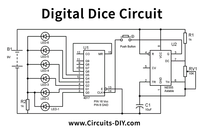
Circuit Diagram
Circuit Operation
In this project, we have utilized 6 LEDs, each LED addressed to a number (1-6) of Dice. LEDs begin blazing as we press the Push switch and stop when we discharge it. After delivery, the enlightened LED addresses the numbers. You jumped on Dice. Like if the fifth number Driven stays ON in the wake of delivering the button, implies you got five on Dice. We have associated 6 LEDs to the yield Q0 to Q5, and the seventh yield, Q6 is associated back to the RESET PIN 15. So that after LED 6, it begins from the First LED at Q0.
In this circuit, we have kept the frequency so high that nobody can trick. LED flashing speed is straightforwardly corresponding to 555 timer IC frequency, as more significant the frequency, as e rate of flashing LED is more significant. You can build frequency as indicated by you, by pivoting the potentiometer.
Applications and Uses
Ludu, snake ladder and many games can be played with dice.