Introduction
Isn’t it fascinating for you to control your home appliances by just sending a message? If you’re a lazy individual, this must-have amuses you to monitor things by just sitting in one place. If you are looking for this, then this tutorial is for you. Because, in this tutorial, we will try to make a device that controls the load appliance with the message sent from the mobile phone. In short, we are going to interface ” 12V Lamp with Arduino UNO”.
However, to send a message from a mobile phone, one must need a GSM module. Since we are using the SIM900 GSM module. Therefore, you first need to assemble it. And, for assembling, you only need to insert your SIM card in the module. Remember that, a module requires 5Volts to operate. Also, it draws almost 2 amps of current. The circuit also needs the relay module to control the 12V lamp. When you connect the relay module to the circuit, make sure to place it in the plastic holder. Since this is essential for safety purposes.
Hardware Required
| S.no | Components | Value | Qty |
|---|---|---|---|
| 1. | Arduino UNO | – | 1 |
| 2. | USB Cable Type A to B | – | 1 |
| 3. | Jumper Wires | – | – |
| 4. | Lamp | 12V | – |
| 5. | Relay | 2-Channel | 1 |
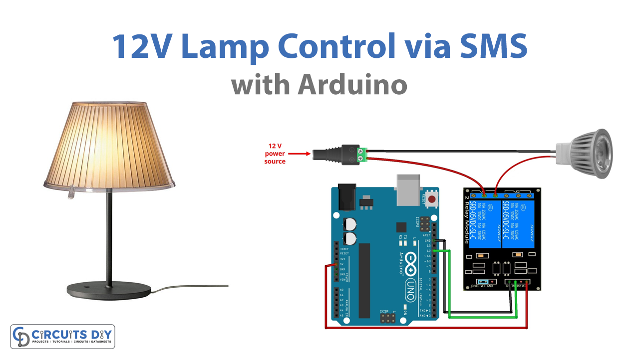
Circuit Diagram

Connection Table
| Arduino | Two Channel Relay |
|---|---|
| VCC | VCC |
| GND | GND |
| D12 | IN 1 |
Arduino Code
#include <SoftwareSerial.h>
// Configure software serial port
SoftwareSerial SIM900(7, 8);

// Variable to store text message
String textMessage;

// Create a variable to store Lamp state
String lampState = "HIGH";

// Relay connected to pin 12
const int relay = 12;

void setup() {
  // Automatically turn on the shield
  digitalWrite(9, HIGH);
  delay(1000);
  digitalWrite(9, LOW);
  delay(5000);

  // Set relay as OUTPUT
  pinMode(relay, OUTPUT);

  // By default the relay is off
  digitalWrite(relay, HIGH);

  // Initializing serial commmunication
  Serial.begin(19200);
  SIM900.begin(19200);

  // Give time to your GSM shield log on to network
  delay(20000);
  Serial.print("SIM900 ready...");

  // AT command to set SIM900 to SMS mode
  SIM900.print("AT+CMGF=1\r");
  delay(100);
  // Set module to send SMS data to serial out upon receipt
  SIM900.print("AT+CNMI=2,2,0,0,0\r");
  delay(100);
}

void loop(){
  if(SIM900.available()>0){
    textMessage = SIM900.readString();
    Serial.print(textMessage);
    delay(10);
  }
  if(textMessage.indexOf("ON")>=0){
    // Turn on relay and save current state
    digitalWrite(relay, LOW);
    lampState = "on";
    Serial.println("Relay set to ON");
    textMessage = "";
  }
  if(textMessage.indexOf("OFF")>=0){
    // Turn off relay and save current state
    digitalWrite(relay, HIGH);
    lampState = "off";
    Serial.println("Relay set to OFF");
    textMessage = "";
  }
  if(textMessage.indexOf("STATE")>=0){
    String message = "Lamp is " + lampState;
    sendSMS(message);
    Serial.println("Lamp state resquest");
    textMessage = "";
  }
}

// Function that sends SMS
void sendSMS(String message){
  // AT command to set SIM900 to SMS mode
  SIM900.print("AT+CMGF=1\r");
  delay(100);

  // REPLACE THE X's WITH THE RECIPIENT'S MOBILE NUMBER
  // USE INTERNATIONAL FORMAT CODE FOR MOBILE NUMBERS
  SIM900.println("AT + CMGS = \"XXXXXXXXXX\"");
  delay(100);
  // Send the SMS
  SIM900.println(message);
  delay(100);

  // End AT command with a ^Z, ASCII code 26
  SIM900.println((char)26);
  delay(100);
  SIM900.println();
  // Give module time to send SMS
  delay(5000);
}
Working Explanation
Connect the 12V Lamp with Arduino UNO and GSM module according to the diagram given above. Now copy the code and paste it into your Arduino IDE. Since the relay is connected to the Arduino. Therefore, when you send the message ON, the Arduino transfers that message to the relay. The relay will get active and will turn ON the lamp. Similarly, when you send the message OFF, the relay will be OFF. Hence, the lamp will be OFF
Code Explanation
- First, we have included the library serial. h to communicate with the serial ports which we have created at digital pins 6 and 7. Then we created the variable text message to keep the message, and lampState to hold the state of the lamp. Since the relay functions on inverted logic. Therefore, initially, we make it high in the code. Then we declared that the relay is connected with digital pin 12.
- In the void setup, we have activated the GSM shield. And, declared the relay as output. Also, we have declared it high to make the relay inactive initially. Then, we initialized the Serial communication and give some delay. This delay is the logging time of the GSM. Then we have given the command to set the module and to send the message.
- Now in the void loop, we have given the three if conditions to the ON the lamp, turn OFF the lamp, and return the state. Then the messages are sent by using the command send SMS( ). Then, there is the function to set the mobile number through which the message will be sent. At last, the delay is to be given to provide some time for the module for sending the message.
Applications and Uses
This circuit is mainly used for home and office automation. But, with some modification, it may be used to control other industrial and commercial devices. For instance, with some improvement, it can be utilized to control motors present in robots, etc. Hence, the circuit has a wide application in every industry.